- 您现在的位置:买卖IC网 > PDF目录170654 > DAC1221EG4 (TEXAS INSTRUMENTS INC) SERIAL INPUT LOADING, 1800 us SETTLING TIME, 16-BIT DAC, PDSO16 PDF资料下载
参数资料
| 型号: | DAC1221EG4 |
| 厂商: | TEXAS INSTRUMENTS INC |
| 元件分类: | DAC |
| 英文描述: | SERIAL INPUT LOADING, 1800 us SETTLING TIME, 16-BIT DAC, PDSO16 |
| 封装: | GREEN, SSOP-16 |
| 文件页数: | 15/16页 |
| 文件大小: | 154K |
| 代理商: | DAC1221EG4 |
8
DAC1221
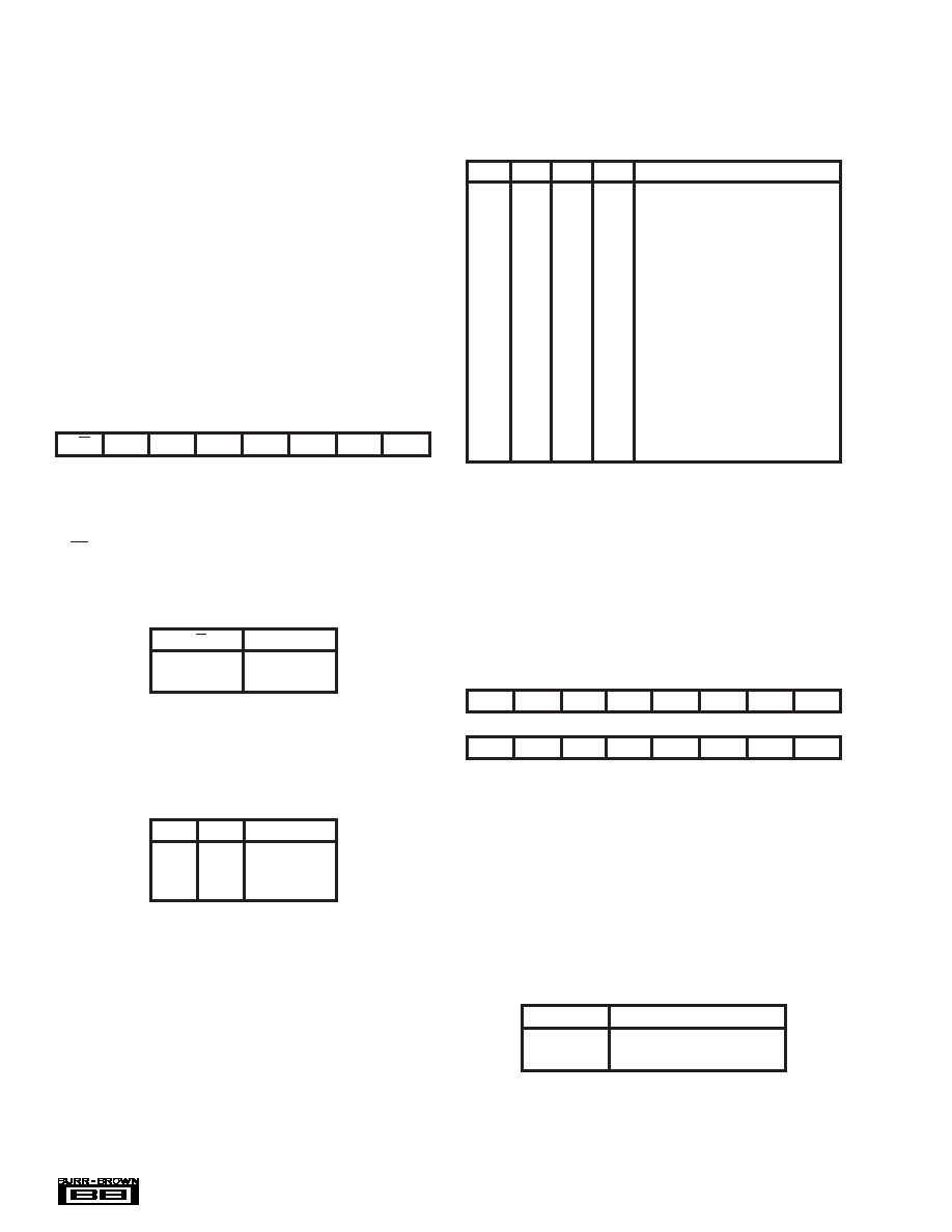
TABLE II. Instruction Register.
MSB
LSB
R/W
MB1
MB0
0
A3
A1
A0
NOTE: INSR is a write-only register with the MSB (Most Significant Byte and
Bit) written first, independent of the BD bit.
A3
A2
A1
A0
0
Data Input Register Byte 1 MSB
0
1
Data Input Register Byte 0 LSB
0
1
0
Reserved
0
1
Reserved
0
1
0
Command Register Byte 1 MSB
0
1
0
1
Command Register Byte 0 LSB
0
1
0
Reserved
0
1
Reserved
1
0
Offset Cal Register Byte 2 MSB
1
0
1
Offset Cal Register Byte 1
1
0
1
0
Offset Cal Register Byte 0 LSB
1
0
1
Reserved
1
0
Full-Scale Cal Register Byte 2 MSB
1
0
1
Full-Scale Cal Register Byte 1
1
0
Full-Scale Cal Register Byte 0 LSB
1
Reserved
TABLE III. A3 - A0 Addressing.
MSB
Byte 1
ADPT
CALPIN
1
0
1
0
CRST
0
Byte 0
LSB
0
CLR
DF
DISF
BD
MSB
MD1
MD0
TABLE IV. Command Register.
R/W
0
Write
1
Read
MB1
MB0
0
1 Byte
0
1
2 Bytes
1
0
3 Bytes
DAC1221 operation mode, settling mode and data format.
The Data Input Register (DIR) contains the value for the
next conversion. The Offset and Full-Scale Calibration Reg-
isters (OCR and FCR) contain data used for correcting the
internal conversion value after it is placed into the DIR. The
data in these two registers may be the result of a calibration
routine, or they may be values which have been written
directly via the serial interface.
INSTRUCTION REGISTER (INSR)
Each serial communication starts with the 8 bits of INSR
being sent to the DAC1221. The read/write bit, the number
of bytes (n), and the starting register address are defined in
Table II. When the n bytes have been transferred, the
instruction is complete. A new communication cycle is
initiated by sending a new INSR (under restrictions outlined
in the Interfacing section).
R/W (Read/Write) Bit—For a write operation to occur, this
bit of the INSR must be 0. For a read, this bit must be 1, as
shown:
MB1, MB0 (Multiple Bytes) Bits—These two bits are used
to control the word length (number of bytes) of the read or
write operation, as shown:
A3 – A0 (Address) Bits—These four bits select the begin-
ning register location that will be read from or written to, as
shown in Table III. Each subsequent byte will be read from
or written to the next higher location (increment address). If
the BD bit in the Command register is set, each subsequent
byte will be read from or written to the next lower location
(decrement address). This bit does not affect INSR register
or the write operation for the CMR register. If the next
location is reserved in Table III, the results are unknown.
Reading or writing continues until the number of bytes
specified by MB1 and MB0 have been transferred.
COMMAND REGISTER (CMR)
The CMR controls all of the functionality of the DAC1221.
The new configuration is latched in on the negative transi-
tion of SCLK for the last bit of the last byte of data being
written to the command register. The organization of the
CMR is comprised of 16 bits of information in 2 bytes of 8
bits each.
ADPT (Adaptive Filter Disable) Bit—The ADPT bit de-
termines if the adaptive filter is enabled or disabled. When
the Adaptive Filter is enabled, the DAC1221 does fast
settling only when there is an output step of larger than
≈ 40mV. For small changes in the data, fast settling is not
necessary. When ADPT = 1, the Adaptive Filter is disabled
and the DAC1221 will not look at the size of a step to
determine the necessity of using fast settling. In either case,
fast settling can be defeated if DISF = 1.
ADPT
0
Enabled (default)
1
Disabled
相关PDF资料 |
PDF描述 |
|---|---|
| DAC5311IDCKR | SERIAL INPUT LOADING, 12 us SETTLING TIME, 8-BIT DAC, PDSO6 |
| DAC5311IDCKRG4 | SERIAL INPUT LOADING, 12 us SETTLING TIME, 8-BIT DAC, PDSO6 |
| DAC5311IDCKTG4 | SERIAL INPUT LOADING, 12 us SETTLING TIME, 8-BIT DAC, PDSO6 |
| DAC5652AIPFBRG4 | DUAL, PARALLEL, WORD INPUT LOADING, 0.02 us SETTLING TIME, 10-BIT DAC, PQFP48 |
| DAC5672AIPFBRG4 | DUAL, PARALLEL, WORD INPUT LOADING, 0.02 us SETTLING TIME, 14-BIT DAC, PQFP48 |
相关代理商/技术参数 |
参数描述 |
|---|---|
| DAC1221LCN | 制造商:n/a 功能描述:1221 |
| DAC1221LCN/A+ | 制造商:未知厂家 制造商全称:未知厂家 功能描述:12-Bit Digital-to-Analog Converter |
| DAC1221LCN/B+ | 制造商:未知厂家 制造商全称:未知厂家 功能描述:12-Bit Digital-to-Analog Converter |
| DAC1222 | 制造商:NSC 制造商全称:National Semiconductor 功能描述:10-Bit, 12-Bit Binary Multiplying D/A Converter |
| DAC1222LCJ | 制造商:Rochester Electronics LLC 功能描述:- Bulk |
发布紧急采购,3分钟左右您将得到回复。