- 您现在的位置:买卖IC网 > PDF目录295503 > DS-11802D4-464Y (DATA DEVICE CORP) DIGITAL TO SYNCHRO OR RESOLVER, CDIP28 PDF资料下载
参数资料
| 型号: | DS-11802D4-464Y |
| 厂商: | DATA DEVICE CORP |
| 元件分类: | 位置变换器 |
| 英文描述: | DIGITAL TO SYNCHRO OR RESOLVER, CDIP28 |
| 封装: | CERAMIC, DDIP-28 |
| 文件页数: | 1/8页 |
| 文件大小: | 341K |
| 代理商: | DS-11802D4-464Y |
DS-11802
FOUR QUADRANT MULTIPLYING SIN/COS DAC,
MICROPROCESSOR COMPATIBLE, 16-BIT HYBRID
DESCRIPTION
The DS-11802 is a small size, high
accuracy, 16-bit digital-to-sine/cosine
converter. Available in accuracies up
to 1 arc minute, the DS-11802 is con-
tained in a 28-pin DDIP and requires
+15 Vdc and -15 Vdc power supplies.
The
reference
input
is
buffered
through an op-amp to minimize load-
ing on the input signal and can accept
up to ±10 V peak. The DS-11802 is
pin programmable for gains of 0.5,
1.0, and 2.0. Two registers for the
input of the 16-bit (CMOS/TTL) natur-
al binary angle data allow for compat-
ibility with an 8-bit or 16-bit data bus.
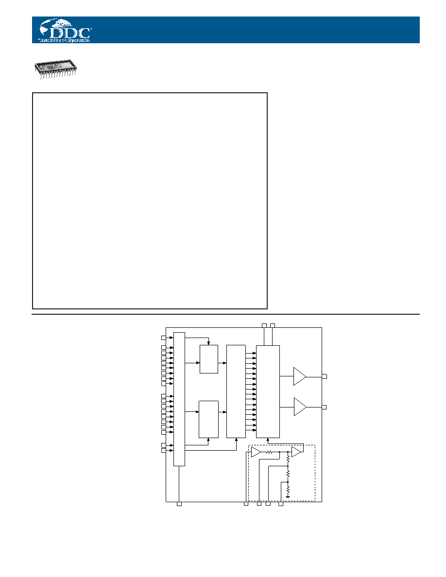
Internally, the DS-11802 has a multi-
plying
digital-to-sin/cos
converter
consisting of two function generators
and a quadrant select network.
Quadrant information is available
from the two most significant bits
(MSBs). The two function generators
use the remaining angular data along
with the buffered reference voltage.
Similar to a multiplying DAC (digital-
to-analog converter), the DS-11802
uses high-accuracy resistive ladder
networks and solid-state switching to
control the attenuation of the refer-
ence voltage. The output buffer ampli-
fiers allow for up to 2 mA output drive.
APPLICATIONS
Due to the high accuracy, high reliabil-
ity, small size, low power consumption
and MIL-PRF-38534 processing avail-
able, the DS-11802 is suitable for
industrial and military ground or avion-
ic applications. Possible applications
include digital remote positioning,
resolver angle simulation, flight train-
ers, flight instrumentation, radar and
navigational systems, and PPI dis-
plays including moving target indica-
tors. Other applications are syn-
chro/resolver system development
and testing, and wraparound test of
synchro/resolver-to-digital converters.
FEATURES
28-Pin Ceramic DDIP Package
1 Arc Minute Accuracy
0.03% Radius Accuracy
Microprocessor Compatible -
8- and 16-Bit
Double-Buffered Inputs
Pin-Programmable Gain -
0.5, 1.0 or 2.0
Buffered Reference Input
DC-Coupled Reference and
Outputs
Requires Only ±15 V Power
Supplies
TTL and CMOS Compatible
Pin-for-Pin Replacement for
Natel’s HDSC2306
9
1
2
3
4
5
6
7
8
11
12
13
14
15
16
17
18
10
19
25
GND
20
23
24
21
28
26
27
VIN
GC1
GC2
REFERENCE
CONDITIONER
BIT16
(LSB)
COS
θ
SIN
θ
BUFFER
AMPLIFIERS
16-BIT
HIGH
ACCURACY
MULTIPLYING
DIGITAL
TO SIN / COS
CONVERTER
16-BIT
HOLDING
REGISTER
BIT 1
(MSB)
Q1
D
Q16
CK
8-BIT
INPUT
REGISTER
CK
8-BIT
INPUT
REGISTER
INPUT
BUFFERS
–V
S
+V
S
HBE
(MSB) B1
B2
B3
B4
B5
B6
B7
B8
B9
B10
B11
B12
B13
B14
B15
(LSB) B16
LBE
LDC
22
TP1
1996, 1999 Data Device Corporation
FIGURE 1. DS-11802 BLOCK DIAGRAM
相关PDF资料 |
PDF描述 |
|---|---|
| DS1075M-60 | 60 MHz, OTHER CLOCK GENERATOR, PDIP8 |
| DS1233Z-10N | 1-CHANNEL POWER SUPPLY SUPPORT CKT, PDSO4 |
| DS1283SN | 1 TIMER(S), REAL TIME CLOCK, PDSO28 |
| DS1543W-120 | 0 TIMER(S), REAL TIME CLOCK, PDIP28 |
| DS1644L-15 | 0 TIMER(S), REAL TIME CLOCK, DSO34 |
相关代理商/技术参数 |
参数描述 |
|---|---|
| DS-11802D4-464Z | 制造商:未知厂家 制造商全称:未知厂家 功能描述:Converter |
| DS-11802D4-465 | 制造商:未知厂家 制造商全称:未知厂家 功能描述:Converter |
| DS-11802D4-465K | 制造商:未知厂家 制造商全称:未知厂家 功能描述:Converter |
| DS-11802D4-465L | 制造商:未知厂家 制造商全称:未知厂家 功能描述:Converter |
| DS-11802D4-465Q | 制造商:未知厂家 制造商全称:未知厂家 功能描述:Converter |
发布紧急采购,3分钟左右您将得到回复。