- 您现在的位置:买卖IC网 > PDF目录9370 > DS1340U-3+T&R (Maxim Integrated Products)IC RTC I2C W/CHARGER 3V 8-USOP PDF资料下载
参数资料
| 型号: | DS1340U-3+T&R |
| 厂商: | Maxim Integrated Products |
| 文件页数: | 3/16页 |
| 文件大小: | 0K |
| 描述: | IC RTC I2C W/CHARGER 3V 8-USOP |
| 产品培训模块: | Lead (SnPb) Finish for COTS Obsolescence Mitigation Program |
| 标准包装: | 3,000 |
| 类型: | 时钟/日历 |
| 特点: | 闰年,方波输出,涓流充电器 |
| 时间格式: | HH:MM:SS(24 小时) |
| 数据格式: | YY-MM-DD-dd |
| 接口: | I²C,2 线串口 |
| 电源电压: | 2.7 V ~ 5.5 V |
| 电压 - 电源,电池: | 1.3 V ~ 3.7 V |
| 工作温度: | -40°C ~ 85°C |
| 安装类型: | 表面贴装 |
| 封装/外壳: | 8-TSSOP,8-MSOP(0.118",3.00mm 宽) |
| 供应商设备封装: | 8-uMAX |
| 包装: | 带卷 (TR) |
have a one-second interval where the calibration is per-
formed. Negative calibration blanks 128 cycles of the
32,768Hz oscillator, slowing the clock down. Positive
calibration inserts 256 cycles of the 32,768Hz oscillator,
speeding the clock up. If a binary 1 is loaded into the
calibration bits, only the first two minutes in the 64-
minute cycle are modified. If a binary 6 is loaded, the
first 12 minutes are affected, and so on. Therefore,
each calibration step either adds 512 or subtracts 256
oscillator cycles for every 125,829,120 actual 32,678Hz
oscillator cycles (64 minutes). This equates to
+4.068ppm or -2.034ppm of adjustment per calibration
step. If the oscillator runs at exactly 32,768Hz, each of
the 31 increments of the calibration bits would repre-
sent +10.7 or -5.35 seconds per month, corresponding
to +5.5 or -2.75 minutes per month.
For example, if using the FT function, a reading of
512.01024Hz would indicate a +20ppm oscillator fre-
quency error, requiring a -10(00 1010) value to be
loaded in the S bit and the five calibration bits.
Note: Setting the calibration bits does not affect the fre-
quency test output frequency. Also note that writing to
the control register resets the divider chain.
I2C Serial Data Bus
The DS1340 supports a bidirectional I2C bus and data
transmission protocol. A device that sends data onto
the bus is defined as a transmitter and a device receiv-
ing data as a receiver. The device that controls the
message is called a master. The devices that are con-
trolled by the master are slaves. A master device that
generates the serial clock (SCL), controls the bus
access, and generates the START and STOP condi-
tions must control the bus. The DS1340 operates as a
slave on the I2C bus. Connections to the bus are made
through the open-drain I/O lines SDA and SCL. Within
the bus specifications a standard mode (100kHz max
clock rate) and a fast mode (400kHz max clock rate)
are defined. The DS1340 works in both modes.
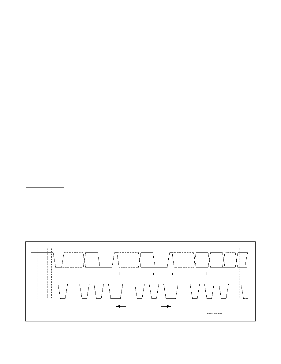
The following bus protocol has been defined (Figure 7):
Data transfer can be initiated only when the bus is
not busy.
During data transfer, the data line must remain
stable whenever the clock line is high. Changes in
the data line while the clock line is high are inter-
preted as control signals.
Accordingly, the following bus conditions have been
defined:
Bus not busy: Both data and clock lines remain
high.
START data transfer: A change in the data line’s
state from high to low, while the clock line is high,
defines a START condition.
STOP data transfer: A change in the data line’s
state from low to high, while the clock line is high,
defines a STOP condition.
Data valid: The data line’s state represents valid
data when, after a START condition, the data line is
stable for the duration of the high period of the
clock signal. The data on the line must be changed
during the low period of the clock signal. There is
one clock pulse per bit of data.
Each data transfer is initiated with a START condi-
tion and terminated with a STOP condition. The
number of data bytes transferred between the
START and STOP conditions is not limited, and is
I2C RTC with Trickle Charger
Maxim Integrated
11
DS1340
SDA
SCL
IDLE
1–7
8
9
1–7
8
9
1–7
8
9
START
CONDITION
STOP CONDITION
REPEATED START
SLAVE
ADDRESS
R/W
ACK
DATA
ACK/
NACK
DATA
MSB FIRST
MSB
LSB
MSB
LSB
REPEATED IF MORE BYTES
ARE TRANSFERRED
Figure 7. I2C Data Transfer Overview
相关PDF资料 |
PDF描述 |
|---|---|
| DS1338Z-18+T&R | IC RTC 56BYTE NV RAM 1.8V 8-SOIC |
| GTC06CF-20-22P | CONN PLUG 6POS STRAIGHT W/PINS |
| DS1340Z-33+T&R | IC RTC I2C W/CHARGER 3.3V 8-SOIC |
| DS1340Z-3+T&R | IC RTC I2C W/CHARGER 3V 8-SOIC |
| VI-J6J-MZ | CONVERTER MOD DC/DC 36V 25W |
相关代理商/技术参数 |
参数描述 |
|---|---|
| DS1340Z-18 | 功能描述:实时时钟 I2C RTC w/Trickle Charger RoHS:否 制造商:Microchip Technology 功能:Clock, Calendar. Alarm RTC 总线接口:I2C 日期格式:DW:DM:M:Y 时间格式:HH:MM:SS RTC 存储容量:64 B 电源电压-最大:5.5 V 电源电压-最小:1.8 V 最大工作温度:+ 85 C 最小工作温度: 安装风格:Through Hole 封装 / 箱体:PDIP-8 封装:Tube |
| DS1340Z-18+ | 功能描述:实时时钟 I2C RTC w/Trickle Charger RoHS:否 制造商:Microchip Technology 功能:Clock, Calendar. Alarm RTC 总线接口:I2C 日期格式:DW:DM:M:Y 时间格式:HH:MM:SS RTC 存储容量:64 B 电源电压-最大:5.5 V 电源电压-最小:1.8 V 最大工作温度:+ 85 C 最小工作温度: 安装风格:Through Hole 封装 / 箱体:PDIP-8 封装:Tube |
| DS1340Z-3 | 功能描述:实时时钟 I2C RTC w/Trickle Charger RoHS:否 制造商:Microchip Technology 功能:Clock, Calendar. Alarm RTC 总线接口:I2C 日期格式:DW:DM:M:Y 时间格式:HH:MM:SS RTC 存储容量:64 B 电源电压-最大:5.5 V 电源电压-最小:1.8 V 最大工作温度:+ 85 C 最小工作温度: 安装风格:Through Hole 封装 / 箱体:PDIP-8 封装:Tube |
| DS1340Z-3/T&R | 制造商:Maxim Integrated Products 功能描述:REAL TIME CLOCK SERL 8SOIC - Tape and Reel |
| DS1340Z-3+ | 功能描述:实时时钟 I2C RTC w/Trickle Charger RoHS:否 制造商:Microchip Technology 功能:Clock, Calendar. Alarm RTC 总线接口:I2C 日期格式:DW:DM:M:Y 时间格式:HH:MM:SS RTC 存储容量:64 B 电源电压-最大:5.5 V 电源电压-最小:1.8 V 最大工作温度:+ 85 C 最小工作温度: 安装风格:Through Hole 封装 / 箱体:PDIP-8 封装:Tube |
发布紧急采购,3分钟左右您将得到回复。