- 您现在的位置:买卖IC网 > PDF目录97868 > DS232AR-N (DALLAS SEMICONDUCTOR) LINE TRANSCEIVER, PDSO16 PDF资料下载
参数资料
| 型号: | DS232AR-N |
| 厂商: | DALLAS SEMICONDUCTOR |
| 元件分类: | Line Driver or Receiver |
| 英文描述: | LINE TRANSCEIVER, PDSO16 |
| 封装: | 0.150 INCH, SOIC-16 |
| 文件页数: | 14/16页 |
| 文件大小: | 224K |
| 代理商: | DS232AR-N |
MAX1501
Highly Integrated, Linear Battery Charger with
Thermal Regulation for Portable Applications
7
Maxim Integrated
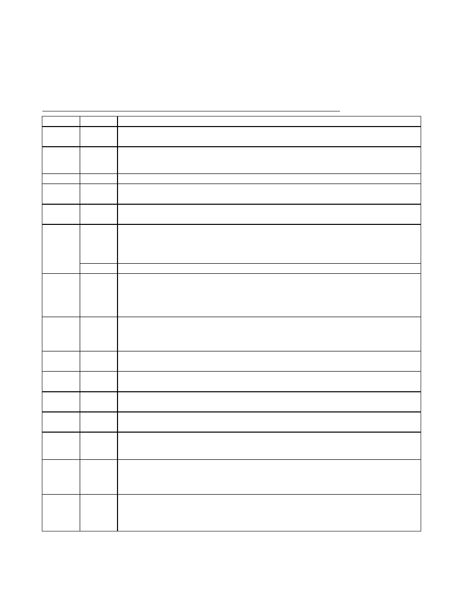
Pin Description
PIN
NAME
FUNCTION
1
INP
High-Current Charger Input. Connect an AC adapter to INP and IN as close to the device as possible.
INP provides charge current to the battery. INP draws current while the device is in shutdown mode.
2IN
Low-Current Charger Input. Bypass IN to GND with a 1F ceramic capacitor. Connect IN to INP as close
to the device as possible. IN powers the internal LDO and reference. IN draws current while the device is
in shutdown mode.
3, 13
GND
Ground. Connect the exposed paddle to GND.
4
SETI
Current-Sense Transconductance Amplifier Output. Connect a resistor from SETI to GND to program the
maximum charge current and to monitor the actual charge current. SETI pulls to GND during shutdown.
5VL
Linear Regulator Output. Connect
CHGEN, TEMP, TMAX, FULLI, and MODE to VL to program logic high.
VL discharges to GND during shutdown.
TMAX
Maximum Charging-Time Select Input (MAX1501 Only). TMAX sets the maximum charging time. Connect
TMAX to GND to set the maximum charging time to 3 hours. Leave TMAX floating to set the maximum
charging time to 4.5 hours. Connect TMAX to VL to set the maximum charging time to 6 hours. TMAX
pulls to GND through a 50k
Ω resistor in shutdown.
6
I.C.
Internally Connected in the MAX1501Z. Leave floating.
7
FULLI
Top-Off-Current Select Input. FULLI sets the end-of-charge threshold as a percentage of the fast-charge
current. Connect FULLI to GND to set the end-of-charge threshold to 10% of the fast-charge current.
Connect FULLI to VL to set the end-of-charge threshold to 20% of the fast-charge current. Leave FULLI
floating to set the end-of-charge threshold to 30% of the fast-charge current. FULLI pulls to GND through
a 50k
Ω resistor in shutdown.
8
TEMP
Die Temperature Select Input. TEMP sets the die temperature regulation point for the thermal-control
loop. Connect TEMP to GND to regulate the die temperature at +95
°C. Leave TEMP floating to regulate
the die temperature at +115
°C. Connect TEMP to VL to regulate the die temperature at +135°C. TEMP
pulls to GND through a 50k
Ω resistor in shutdown.
9
MODE
Mode Select Input.
MODE and CHGEN together control charging functions (Table 1). An internal 175k
Ω
pulldown resistor pulls
MODE low.
10
CHGEN
Charge Enable Input.
CHGEN and MODE together control charging functions (Table 1). An internal
175k
Ω pulldown resistor pulls CHGEN low.
11
ACOK
Input Voltage Range Indicator. The open-drain
ACOK output asserts low when 4.2V
≤ VIN ≤ 6.25V and
VIN - VBATT
≥ 100mV. ACOK requires an external 100kΩ pullup resistor. ACOK floats in shutdown.
12
BATT
Battery Connection. Connect the positive terminal of the battery to BATT. BATT draws less than 5A
during shutdown.
14
SELV
Battery Voltage Selection Input. SELV sets the battery regulation voltage in Li+ and NiMH/NiCd modes
(Table 2). For no-battery mode, the battery voltage defaults to 4.0V. An internal 175k
Ω resistor to VL pulls
SELV high.
15
RLED
Battery Charging Indicator. Connect the anode of a red LED to IN and the cathode to
RLED. RLED
asserts low when the input supply is present and the battery is charging, regardless of cell chemistry.
RLED sinks 10mA. RLED goes high impedance in shutdown. Connect a pullup resistor to the P’s I/O
supply when interfacing with a P logic input.
16
GLED
Full-Charge Indicator. Connect the anode of a green LED to IN and the cathode to
GLED. GLED asserts
low when the input supply is present and the battery has reached the top-off current threshold set by
FULLI, regardless of cell chemistry.
GLED sinks 20mA. GLED goes high impedance in shutdown.
Connect a pullup resistor to the P’s I/O supply when interfacing with a P logic input.
相关PDF资料 |
PDF描述 |
|---|---|
| DS232AS-N | LINE TRANSCEIVER, PDSO16 |
| DS232AS | LINE TRANSCEIVER, PDSO16 |
| DS232A | LINE TRANSCEIVER, PDIP16 |
| DS2404S-001 | 0 TIMER(S), REAL TIME CLOCK, PDSO16 |
| DS2404B | 0 TIMER(S), REAL TIME CLOCK, PDSO16 |
相关代理商/技术参数 |
参数描述 |
|---|---|
| DS232AR-N/T&R | 制造商:Rochester Electronics LLC 功能描述: 制造商:Maxim Integrated Products 功能描述:IC TXRX DL RS-232 5V IND 16-SOIC |
| DS232AR-N/T&R | 功能描述:RS-232接口集成电路 RoHS:否 制造商:Exar 数据速率:52 Mbps 工作电源电压:5 V 电源电流:300 mA 工作温度范围:- 40 C to + 85 C 安装风格:SMD/SMT 封装 / 箱体:LQFP-100 封装: |
| DS232AR-N+ | 功能描述:RS-232接口集成电路 RoHS:否 制造商:Exar 数据速率:52 Mbps 工作电源电压:5 V 电源电流:300 mA 工作温度范围:- 40 C to + 85 C 安装风格:SMD/SMT 封装 / 箱体:LQFP-100 封装: |
| DS232AR-N+T&R | 制造商:Maxim Integrated Products 功能描述:IC TXRX DUAL RS-232 5V 16-SOIC |
| DS232AR-N+T&R | 功能描述:RS-232接口集成电路 RoHS:否 制造商:Exar 数据速率:52 Mbps 工作电源电压:5 V 电源电流:300 mA 工作温度范围:- 40 C to + 85 C 安装风格:SMD/SMT 封装 / 箱体:LQFP-100 封装: |
发布紧急采购,3分钟左右您将得到回复。