- 您现在的位置:买卖IC网 > PDF目录97868 > DS232AR-N (DALLAS SEMICONDUCTOR) LINE TRANSCEIVER, PDSO16 PDF资料下载
参数资料
| 型号: | DS232AR-N |
| 厂商: | DALLAS SEMICONDUCTOR |
| 元件分类: | Line Driver or Receiver |
| 英文描述: | LINE TRANSCEIVER, PDSO16 |
| 封装: | 0.150 INCH, SOIC-16 |
| 文件页数: | 3/16页 |
| 文件大小: | 224K |
| 代理商: | DS232AR-N |
MAX1501
Highly Integrated, Linear Battery Charger with
Thermal Regulation for Portable Applications
11
Maxim Integrated
Li+ Charge Mode
Connect CHGEN and MODE to GND to place the
MAX1501 in Li+ charging mode. The Li+ charger con-
sists of a voltage-control loop, a current-control loop,
and a thermal-control loop. Connect SELV to GND to
set the Li+ battery voltage to 4.1V. Connect SELV to VL
to set the Li+ battery voltage to 4.2V (Table 2).
The MAX1501 precharges the Li+ battery with 10% of
the user-programmed fast-charge current at the start of
a charge cycle. A soft-start algorithm ramps up the
charging current (10% steps with 20ms duration per
step) to the fast-charge current when the battery volt-
age reaches 2.8V. The MAX1501 enters constant-volt-
age mode and decreases the charge current when the
BATT voltage reaches the selected regulation voltage
(4.1V or 4.2V). Set the fast-charge current with a resis-
tor between SETI and GND (see the
Charge-Current
Selection section).
The thermal-regulation loop limits the MAX1501 die
temperature to the value selected by the TEMP input by
reducing the charge current as necessary (see the
Thermal-Regulation Selection section). This feature not
only protects the MAX1501 from overheating, but also
allows the charge current to be set higher without
risking damage to the system.
Set the top-off-current threshold with the three-state
FULLI input (see the
Top-Off-Current Selection section).
RLED goes high impedance and GLED asserts low when
the top-off-current threshold is reached. The MAX1501
automatically initiates recharging when the battery volt-
age drops below 95% of the voltage set by SELV. (The
MAX1501Z does not time out.)
NiMH/NiCd Charge Mode
Connect MODE to VL to place the MAX1501 in
NiMH/NiCd charging mode. NiMH/NiCd mode uses only
current- and voltage-control loops, and is intended for
trickle- or timer-based chargers. Fast charge termination
schemes, such as negative
ΔV or ΔT, are not included in
the MAX1501 but can be implemented using an external
microcontroller. Trickle- or timer-based chargers should
connect SELV to GND to set the regulation voltage to
4.5V. P controlled chargers should connect SELV to VL
SELV
CHARGING MODE
GND
VL
Li+
4.1V
4.2V
NiMH/NiCd
4.5V
4.95V
Table 2. Battery Regulation Voltage
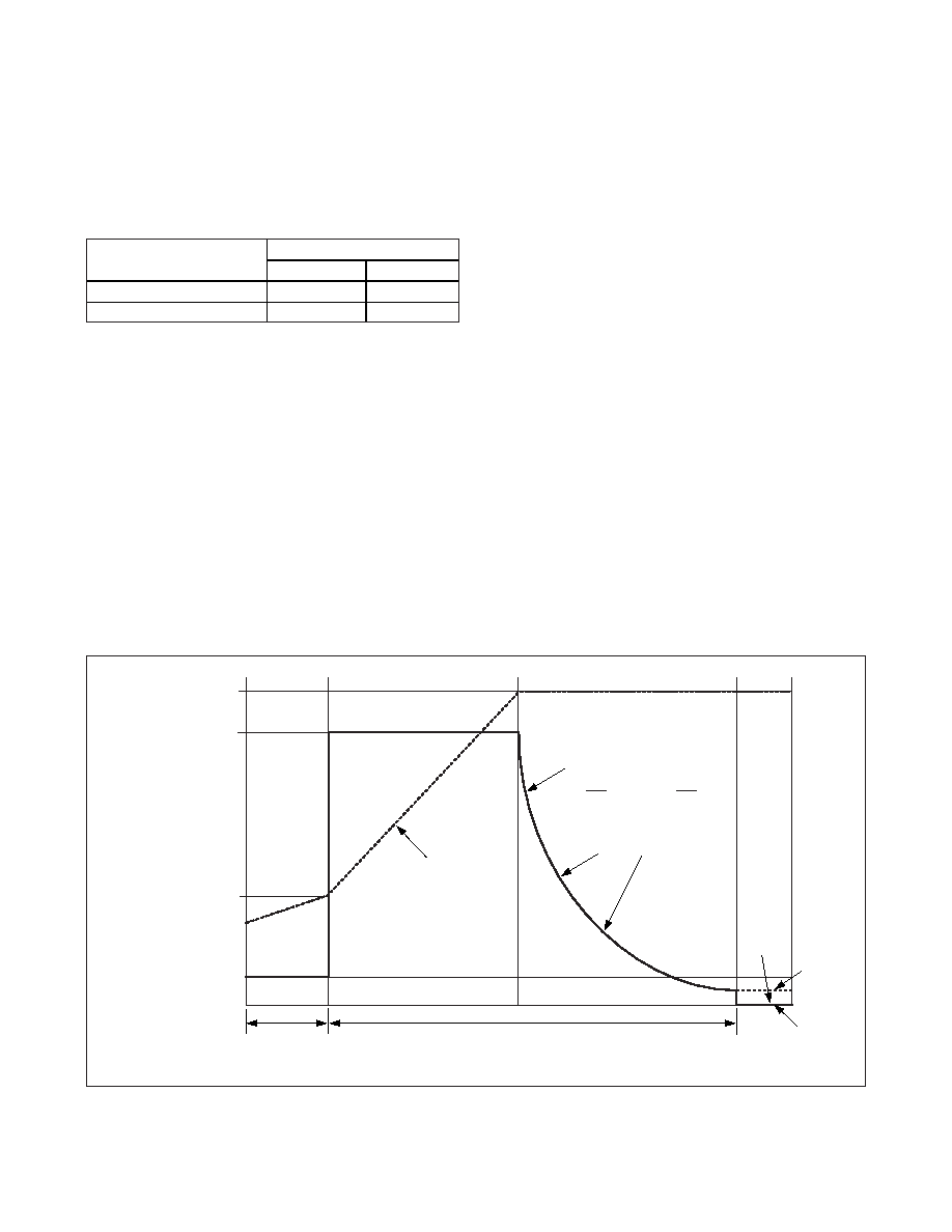
PREQUALIFICATION
REGULATION VOLTAGE
FAST-CHARGE CURRENT
MINIMUM CHARGE VOLTAGE
(2.8V)
FAST CHARGING
TOP-OFF
BATTERY
VOLTAGE
BATTERY
CURRENT
CHARGE
TERMINATED
10% OF FAST-CHARGE CURRENT
DONE
RLED TURNS OFF AND GLED
TURNS ON WHEN CHARGE CURRENT
DROPS TO VALUE SET BY FULLI
(10%, 20%, OR 30% OF FAST-
CHARGE CURRENT).
tPREQUAL
tMAX
MAX1501Z
MAX1501
Figure 4. Li+ Charge Sequence
相关PDF资料 |
PDF描述 |
|---|---|
| DS232AS-N | LINE TRANSCEIVER, PDSO16 |
| DS232AS | LINE TRANSCEIVER, PDSO16 |
| DS232A | LINE TRANSCEIVER, PDIP16 |
| DS2404S-001 | 0 TIMER(S), REAL TIME CLOCK, PDSO16 |
| DS2404B | 0 TIMER(S), REAL TIME CLOCK, PDSO16 |
相关代理商/技术参数 |
参数描述 |
|---|---|
| DS232AR-N/T&R | 制造商:Rochester Electronics LLC 功能描述: 制造商:Maxim Integrated Products 功能描述:IC TXRX DL RS-232 5V IND 16-SOIC |
| DS232AR-N/T&R | 功能描述:RS-232接口集成电路 RoHS:否 制造商:Exar 数据速率:52 Mbps 工作电源电压:5 V 电源电流:300 mA 工作温度范围:- 40 C to + 85 C 安装风格:SMD/SMT 封装 / 箱体:LQFP-100 封装: |
| DS232AR-N+ | 功能描述:RS-232接口集成电路 RoHS:否 制造商:Exar 数据速率:52 Mbps 工作电源电压:5 V 电源电流:300 mA 工作温度范围:- 40 C to + 85 C 安装风格:SMD/SMT 封装 / 箱体:LQFP-100 封装: |
| DS232AR-N+T&R | 制造商:Maxim Integrated Products 功能描述:IC TXRX DUAL RS-232 5V 16-SOIC |
| DS232AR-N+T&R | 功能描述:RS-232接口集成电路 RoHS:否 制造商:Exar 数据速率:52 Mbps 工作电源电压:5 V 电源电流:300 mA 工作温度范围:- 40 C to + 85 C 安装风格:SMD/SMT 封装 / 箱体:LQFP-100 封装: |
发布紧急采购,3分钟左右您将得到回复。