- 您现在的位置:买卖IC网 > PDF目录1994 > DS2417X/T&R (Maxim Integrated Products)IC TIMECHIP W/INTRPT 1WIRE CSP PDF资料下载
参数资料
| 型号: | DS2417X/T&R |
| 厂商: | Maxim Integrated Products |
| 文件页数: | 11/15页 |
| 文件大小: | 0K |
| 描述: | IC TIMECHIP W/INTRPT 1WIRE CSP |
| 标准包装: | 10,000 |
| 类型: | 二进制计数器 |
| 特点: | 唯一 ID |
| 时间格式: | 二进制 |
| 数据格式: | 二进制 |
| 接口: | 1 线 串行 |
| 电源电压: | 2.5 V ~ 5.5 V |
| 工作温度: | -40°C ~ 85°C |
| 安装类型: | 表面贴装 |
| 封装/外壳: | 6-XBGA,FCBGA |
| 供应商设备封装: | 6-覆晶(2.82x2.54) |
| 包装: | 带卷 (TR) |

DS2417
Bit 4 - 6
IS
Interval Select
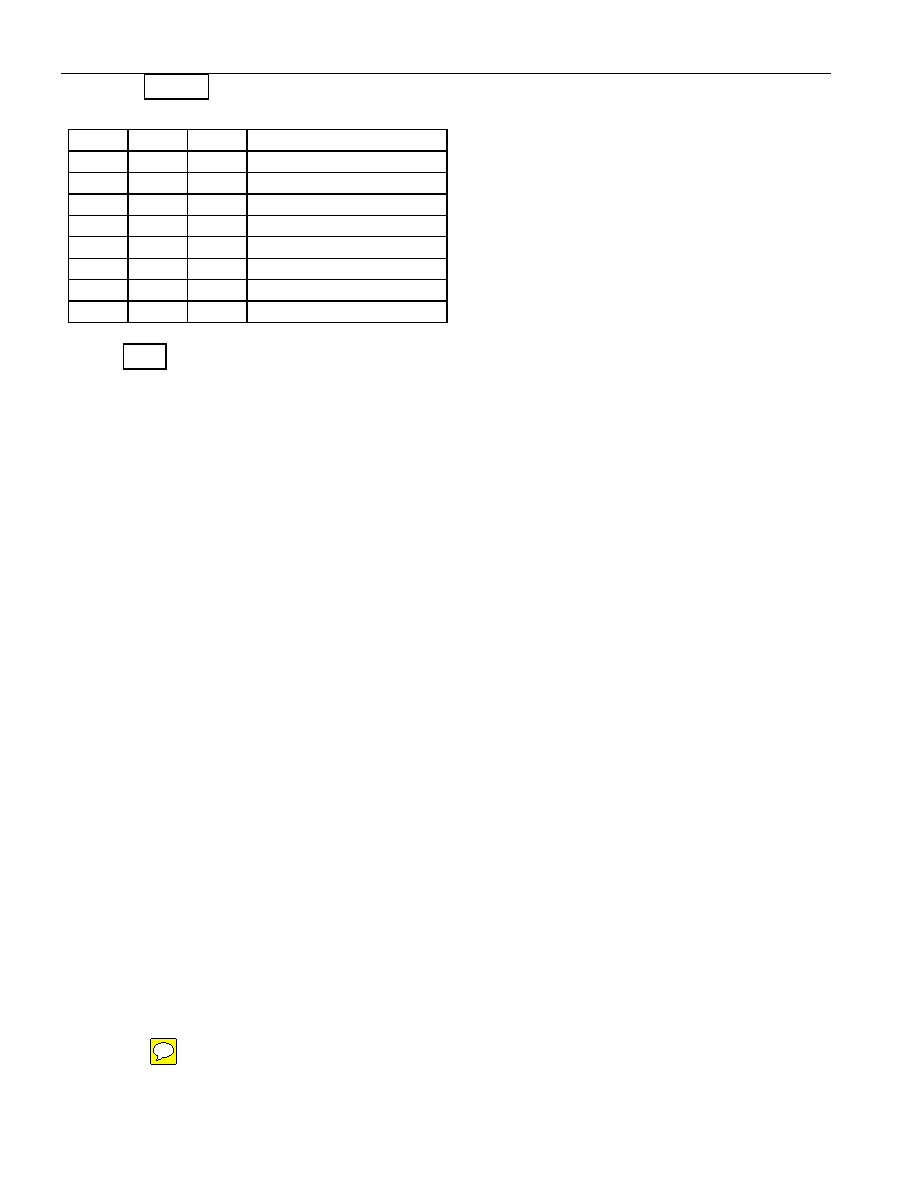
These bits determine the time between interrupt pulses. The values available are shown below.
IS2
IS1
IS0
Interrupt Interval
0
1s
0
1
4s
0
1
0
32s
= 0.53 min.
0
1
64s
= 1.07 min.
1
0
2048s
= 34.13 min.
1
0
1
4096s
= 68.27 min.
1
0
65536s = 18.20 hours
1
131072s = 36.41 hours
Bit 7 IE Interrupt Enable
This bit controls whether the interrupt pulse will be generated at the selected interval. To enable
interrupts this bit needs to be 1.
REAL-TIME CLOCK
The real-time clock is a 32-bit binary counter. It is incremented once per second. The real-time clock
can accumulate 136 years of seconds before rolling over. Time/date is represented by the number of
seconds since a reference point, which is determined by the user. For example, 12:00 a.m., January 1,
1970 could be a reference point.
CLOCK FUNCTION COMMANDS
The “Clock Function Flow Chart” (Figure 5) describes the protocols necessary for accessing the real-time
clock. With only four bytes of real-time clock and one control byte the DS2417 does not provide random
access. Reading and writing always starts with the device control byte followed by the least significant
byte of the time data.
READ CLOCK [66h]
The read clock command is used to read the device control byte and the contents of the real-time clock
counter. After having received the most significant bit of the command code the device copies the actual
contents of the real-time clock counter to the read/write buffer. Now, the bus master reads data beginning
with the device control byte followed by the least significant byte through the most significant byte of the
real-time clock. After this the bus master may continue reading from the DS2417. The data received will
be the same as in the first pass through the command flow. The read clock command can be ended at any
point by issuing a Reset Pulse.
WRITE CLOCK [99h]
The write clock command is used to set the real-time clock counter and to write the device control byte.
After issuing the command, the bus master writes first the device control byte, which becomes immedi-
ately effective. After this the bus master sends the least significant byte through the most significant byte
to be written to the real-time clock counter. The new time data is copied from the read/write buffer to the
real-time clock counter and becomes effective as the bus master generates a reset pulse. If enabled, an
interrupt pulse will be generated either immediately or delayed, depending on the actual time and the se-
lected interval duration (see Figure 11). If the oscillator is intentionally stopped the real-time clock
counter behaves as a four-byte nonvolatile memory.
5 of 15
相关PDF资料 |
PDF描述 |
|---|---|
| DS26502LN+ | IC T1/E1/J1 64KCC ELEMENT 64LQFP |
| DS26503LN+ | IC T1/E1/J1 BITS ELEMENT 64-LQFP |
| DS3105LN+ | IC TIMING LINE CARD 64-LQFP |
| DS3106LN+ | IC TIMING LINE CARD 64-LQFP |
| DS3231MZ+ | IC RTC I2C 8SOIC |
相关代理商/技术参数 |
参数描述 |
|---|---|
| DS2421FP000 | 制造商:Thomas & Betts 功能描述:200A,CON,3P4W,MG,421,3P440V |
| DS2421FR000 | 制造商:Thomas & Betts 功能描述:200A,REC,3P4W,MG,421,3P440V |
| DS2421FRA00 | 制造商:Thomas & Betts 功能描述:200A,REC,3P4W,MG,421,AGL,3P440V |
| DS2421FRAB0 | 制造商:Thomas & Betts 功能描述:200A,REC,3P4W,MG,421,AB0,3P440V |
| DS2421FRABK | 制造商:Thomas & Betts 功能描述:200A,REC,3P4W,MG,421,ABK,3P440V |
发布紧急采购,3分钟左右您将得到回复。