参数资料
| 型号: | DS3153+ |
| 厂商: | Maxim Integrated Products |
| 文件页数: | 6/61页 |
| 文件大小: | 0K |
| 描述: | IC LIU DS3/E3/STS-1 144-CSBGA |
| 产品培训模块: | Lead (SnPb) Finish for COTS Obsolescence Mitigation Program |
| 标准包装: | 160 |
| 类型: | 线路接口装置(LIU) |
| 驱动器/接收器数: | 2/2 |
| 规程: | DS3 |
| 电源电压: | 3.135 V ~ 3.465 V |
| 安装类型: | 表面贴装 |
| 封装/外壳: | 144-BGA,CSPBGA |
| 供应商设备封装: | 144-TECSBGA(13x13) |
| 包装: | 托盘 |
第1页第2页第3页第4页第5页当前第6页第7页第8页第9页第10页第11页第12页第13页第14页第15页第16页第17页第18页第19页第20页第21页第22页第23页第24页第25页第26页第27页第28页第29页第30页第31页第32页第33页第34页第35页第36页第37页第38页第39页第40页第41页第42页第43页第44页第45页第46页第47页第48页第49页第50页第51页第52页第53页第54页第55页第56页第57页第58页第59页第60页第61页
DS3151/DS3152/DS3153/DS3154 Single/Dual/Triple/Quad DS3/E3/STS-1 LIUs
14 of 61
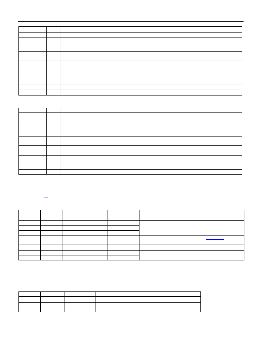
NAME
I/O
FUNCTION
transaction, with R/
W = 1 indicating a read and R/W = 0 indicating a write.
RD/DS
I
Read Enable (Active Low) or Data Strobe (Active Low). In Intel bus mode (MOT = 0),
RD is asserted
to read internal registers. In Motorola bus mode (MOT = 1), the rising edge of
DS writes data to
internal registers.
A[5:0]
I
Address Bus. These inputs specify the address of the internal register to be accessed. A5 is not
present on the DS3152. A5 and A4 are not present on the DS3151.
D[7:0]
I/O
Data Bus. These bidirectional lines are inputs during writes to internal registers. They are outputs
during reads from internal registers.
INT
O
Interrupt Output (Active Low, Open Drain). This pin is forced low in response to one or more
unmasked, active interrupt sources within the device.
INT remains low until the interrupt is serviced or
masked.
VDD
P
Positive Supply. 3.3V
±5%. All V
DD signals should be wired together.
VSS
P
Ground Reference. All VSS signals should be wired together.
Table 4-E. JTAG and Test Pin Descriptions
NAME
I/O
FUNCTION
JTCLK
I
JTAG IEEE 1149.1 Test Serial Clock. JTCLK shifts data into JTDI on the rising edge and out of
JTDO on the falling edge. If boundary scan is not used, JTCLK should be pulled high.
JTDI
IPU
JTAG IEEE 1149.1 Test Serial-Data Input (Internal 10k
Ω Pullup). Test instructions and data are
clocked in on this pin on the rising edge of JTCLK. If boundary scan is not used, JTDI should be left
unconnected or pulled high.
JTDO
O
JTAG IEEE 1149.1 Test Serial-Data Output. Test instructions and data are clocked out on this pin on
the falling edge of JTCLK.
JTRST
IPU
JTAG IEEE 1149.1 Test Reset (Internal 10k
Ω Pullup). This pin is used to asynchronously reset the
test access port (TAP) controller. If boundary scan is not used,
JTRST can be held low or high.
JTMS
IPU
JTAG IEEE 1149.1 Test Mode Select (Internal 10k
Ω Pullup). This pin is sampled on the rising edge
of JTCLK and is used to place the port into the various defined IEEE 1149.1 states. If boundary scan
is not used, JTMS should be left unconnected or pulled high.
TEST
IPU
Factory Test Pin. Leave unconnected or wire high for normal operation.
Note 1: Pin type I = input pin. Pin type O = output pin. Pin type P = power-supply pin.
Note 2: Pin type O3 is an output that can be tri-stated.
Note 3: Pin type IPU is an input with an internal 10kΩ pullup.
Note 4: For pin names of the form PINn, n = LIU# = 1, 2, 3, or 4. PIN1 is on LIU 1, PIN2 is on LIU 2, etc.
Note 5: Section 14 shows hardware mode and CPU bus mode pin assignments.
Table 4-F. Transmitter Data Select Options
TDSA
TDSB
E3M
STS
Tx MODE
TRANSMIT DATA SELECTED
0
X
Any
Normal data as input at TPOS and TNEG
0
1
0
DS3
0
1
0
E3
0
1
STS-1
Unframed all ones
0
1
0
1
DS3
DS3 AIS per ANSI T1.107 (Figure 7-2)
1
0
X
Any
Unframed 100100… pattern
1
0
E3
2
23 - 1 PRBS pattern per ITU O.151
1
0
X
DS3
1
STS-1
2
15 - 1 PRBS pattern per ITU O.151
Note 1: This coding of the TDSA, TDSB, E3M, and STS bits allows AIS generation to be enabled by holding TDSA = 0 and changing TDSB
from 0 to 1. The type of DS3 AIS signal is selected by the STS bit with E3M = 0.
Note 2: If E3M and/or STS are changed when {TDSA,TDSB}
≠ 00, TDSA and TDSB must both be cleared to 0. After they are cleared, TDSA
and TDSB can be configured to transmit a pattern in the new operating mode.
Table 4-G. Receiver PRBS Pattern Select Options
E3M
STS
Rx MODE
RECEIVER PRBS PATTERN SELECTED
1
0
E3
2
23 - 1 PRBS pattern per ITU O.151
0
X
DS3
1
STS-1
2
15 - 1 PRBS pattern per ITU O.151
相关PDF资料 |
PDF描述 |
|---|---|
| MAX1238LEEE+T | IC ADC 12BIT SERIAL 16-QSOP |
| MS27473T24B19PA | CONN PLUG 19POS STRAIGHT W/PINS |
| VE-B10-IV-B1 | CONVERTER MOD DC/DC 5V 150W |
| VI-2TR-MX-F2 | CONVERTER MOD DC/DC 7.5V 75W |
| DS26528GA5+ | IC TXRX T1/E1/J1 OCT 256-CSBGA |
相关代理商/技术参数 |
参数描述 |
|---|---|
| DS3153+ | 功能描述:网络控制器与处理器 IC Triple DS3/E3/STS-1 Line Interface Unit RoHS:否 制造商:Micrel 产品:Controller Area Network (CAN) 收发器数量: 数据速率: 电源电流(最大值):595 mA 最大工作温度:+ 85 C 安装风格:SMD/SMT 封装 / 箱体:PBGA-400 封装:Tray |
| DS3153DK | 功能描述:网络开发工具 DS3153 Dev Kit RoHS:否 制造商:Rabbit Semiconductor 产品:Development Kits 类型:Ethernet to Wi-Fi Bridges 工具用于评估:RCM6600W 数据速率:20 Mbps, 40 Mbps 接口类型:802.11 b/g, Ethernet 工作电源电压:3.3 V |
| DS3153N | 功能描述:网络控制器与处理器 IC Triple DS3/E3/STS-1 Line Interface Unit RoHS:否 制造商:Micrel 产品:Controller Area Network (CAN) 收发器数量: 数据速率: 电源电流(最大值):595 mA 最大工作温度:+ 85 C 安装风格:SMD/SMT 封装 / 箱体:PBGA-400 封装:Tray |
| DS3153N# | 功能描述:网络控制器与处理器 IC Triple DS3/E3/STS-1 Line Interface Unit RoHS:否 制造商:Micrel 产品:Controller Area Network (CAN) 收发器数量: 数据速率: 电源电流(最大值):595 mA 最大工作温度:+ 85 C 安装风格:SMD/SMT 封装 / 箱体:PBGA-400 封装:Tray |
| DS3153N+ | 功能描述:网络控制器与处理器 IC Triple DS3/E3/STS-1 Line Interface Unit RoHS:否 制造商:Micrel 产品:Controller Area Network (CAN) 收发器数量: 数据速率: 电源电流(最大值):595 mA 最大工作温度:+ 85 C 安装风格:SMD/SMT 封装 / 箱体:PBGA-400 封装:Tray |
发布紧急采购,3分钟左右您将得到回复。