- 您现在的位置:买卖IC网 > PDF目录9189 > DS3503U+T&R (Maxim Integrated Products)IC POT DGTL NV 128TAP 10-MSOP PDF资料下载
参数资料
| 型号: | DS3503U+T&R |
| 厂商: | Maxim Integrated Products |
| 文件页数: | 10/13页 |
| 文件大小: | 0K |
| 描述: | IC POT DGTL NV 128TAP 10-MSOP |
| 产品培训模块: | Lead (SnPb) Finish for COTS Obsolescence Mitigation Program |
| 标准包装: | 3,000 |
| 接片: | 128 |
| 电阻(欧姆): | 5k |
| 电路数: | 2 |
| 温度系数: | 标准值 4 ppm/°C |
| 存储器类型: | 非易失 |
| 接口: | I²C(设备位址) |
| 电源电压: | 2.7 V ~ 3.6 V |
| 工作温度: | -40°C ~ 100°C |
| 安装类型: | 表面贴装 |
| 封装/外壳: | 10-TFSOP,10-MSOP(0.118",3.00mm 宽) |
| 供应商设备封装: | 10-µMAX |
| 包装: | 带卷 (TR) |
DS3503
NV, I2C, Stepper Potentiometer
6
_______________________________________________________________________________________
Detailed Description
The DS3503 contains two potentiometers whose out-
puts can be stepped up and down by configuring the
control registers. One potentiometer, with output RW, is
controlled by the Initial Value Register/Wiper Register
(IVR/WR). The other potentiometer is fixed at setting
40h, and its output is on the Y pin. By using the config-
uration registers and the SYNC pin, the outputs from
these two potentiometers can be stepped up and
down.
Digital Potentiometers
The RW potentiometer consists of 127 resistors in
series connected between the RH and RL pins.
Between each resistance and at the two end points, RH
and RL, solid-state switches enable RW to be connect-
ed within the resistive network. The wiper position and
the output on RW are decoded based on the value in
WR. If RH, RL, and RW are externally connected in a
voltage-divider configuration, the voltage on RW can be
easily calculated using the following equation:
Where WR is the wiper position in decimal (0–127). The
factory default setting for this potentiometer is 40h.
The Y potentiometer is also referenced to the RH and
RL terminals, but is centered at a 40h setting.
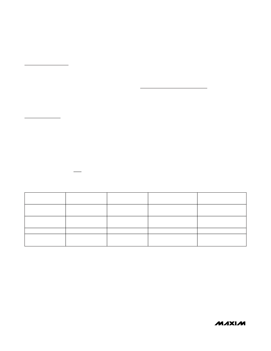
Memory Map
The DS3503 contains three registers for controlling the
outputs of the two potentiometers, pins RW and Y.
Table 1 shows the memory map. IVR/WR is accessed
at register address 00h and contains the power-on and
current values of the RW potentiometer. The Step
Control Register (SCR) controls the stepping function
for both potentiometers. The Control Register (CR) con-
trols the write functionality of the IVR/WR.
Initial Value Register/Wiper Register
(IVR/WR)
Programming IVR sets the initial power-up value of the
RW wiper position. IVR/WR can be visualized as a
volatile register (WR) in parallel with a nonvolatile regis-
ter (IVR). On power-up, the data stored in IVR is loaded
into WR, which sets the position of the potentiometer’s
wiper. The factory default value for IVR is 40h. See the
Stepping section for information about clamping.
VV
WR
VV
RW
RL
RH
RL
=+
×
127
()
NAME
ADDRESS
(HEX)
ACCESS
NONVOLATILE
VOLATILE
IVR/WR
00h
R/W
Initial Value Register (IVR),
factory setting = 40h
Wiper Register (WR)
SCR
01h
R/W
Step Control Register,
factory setting = 00h
—
CR
02h
R/W
Control Register
—
Soft-POR
AAh
R/W
—
Soft Power-On Reset
Register
Table 1. Memory Map
相关PDF资料 |
PDF描述 |
|---|---|
| VI-2W0-MW | CONVERTER MOD DC/DC 5V 100W |
| VI-2V4-MX-B1 | CONVERTER MOD DC/DC 48V 75W |
| VI-2VM-MX-B1 | CONVERTER MOD DC/DC 10V 75W |
| DS1841X | IC RES LOG NV I2C DGTL 10TDFN |
| VI-2V2-MX-B1 | CONVERTER MOD DC/DC 15V 75W |
相关代理商/技术参数 |
参数描述 |
|---|---|
| DS3504FP000 | 制造商:Thomas & Betts 功能描述:30A,PLG,3P4W,MG,404,000,3P480V,FC |
| DS3504FP00K | 制造商:Thomas & Betts 功能描述:30A,CON,3P4W,MG,504,00K,3P480V,FC |
| DS3504FP00K/JG63 | 制造商:Thomas & Betts 功能描述:30A,CON,3P4W,504,00K,3P480V,FC,JG63 |
| DS3504FP00K/JG64 | 制造商:Thomas & Betts 功能描述:30A,CON,3P4W,MG,504,3P480V,JG64 |
| DS3504FP00K/JG66 | 制造商:Thomas & Betts 功能描述:30A,CON,3P4W,MG,504,3P480V,JG66 |
发布紧急采购,3分钟左右您将得到回复。