- 您现在的位置:买卖IC网 > PDF目录2068 > DS3510T+ (Maxim Integrated Products)IC I2C GAMMA/VCOM BUFF 48-TQFN PDF资料下载
参数资料
| 型号: | DS3510T+ |
| 厂商: | Maxim Integrated Products |
| 文件页数: | 3/17页 |
| 文件大小: | 0K |
| 描述: | IC I2C GAMMA/VCOM BUFF 48-TQFN |
| 产品培训模块: | Lead (SnPb) Finish for COTS Obsolescence Mitigation Program |
| 标准包装: | 209 |
| 应用: | TFT-LCD 面板:伽玛缓冲器,VCOM 驱动器 |
| 输出类型: | 满摆幅 |
| 电路数: | 10 |
| 电流 - 电源: | 6.7mA |
| 电流 - 输出 / 通道: | 4mA |
| 电压 - 电源,单路/双路(±): | 9 V ~ 15 V |
| 安装类型: | 表面贴装 |
| 封装/外壳: | 48-WFQFN 裸露焊盘 |
| 供应商设备封装: | 48-TQFN-EP(7x7) |
| 包装: | 管件 |
DS3510
I2C Gamma and VCOM Buffer with EEPROM
______________________________________________________________________________________
11
like the other modes, the LD pin determines when the
DACs get updated. If the LD signal is high, Latch B is
flow-through and the DAC is updated immediately. If
LD is low, Latch B will be loaded from Latch A after a
low-to-high transition on the LD pin. This latter method
allows the timing of the DAC update to be controlled by
an external signal pulse.
VCOM/Gamma Channel Outputs
As illustrated in the
Block Diagram, the VCOM and
gamma channel outputs are equivalent to an 8-bit digi-
tal potentiometer (DAC) with a buffered output. The
VCOM channel’s digital potentiometer is comprised of
255 equal resistive elements. The relationship between
output voltage and DAC setting is illustrated in Table 3.
Unlike the gamma channels, the VCOM channel is
capable of outputting a range of voltages including
both references (VRH and VRL). Each of the gamma
channel digital potentiometers, on the other hand, are
comprised of 256 equal resistive elements. The extra
resistive element prohibits one of the rails from being
reached. In particular, gamma channel outputs
GM1–GM5 can span from (and including) GLL to 1 LSB
away from GLM. Likewise, gamma channel outputs
GM6–GM10 span from (and including) GHM to 1 LSB
away from GHH. The relationship between output volt-
age and DAC setting for the gamma channels is also
illustrated in Table 3.
Standby Mode
Standby mode (not to be confused with the three
DS3510 operating modes) can be used to minimize
current consumption. Standby mode is entered by set-
ting the standby bit, which is the LSB of register 51h.
The VCOM and gamma outputs are placed in a high-
impedance state. Current drawn from the VDD supply in
this state is specified as IDDQ.
The DS3510 continues to respond to I2C commands,
and thus draws some current from VCC when I2C activi-
ty is occurring. When the I2C interface is inactive, cur-
rent drawn from the VCC supply is specified as ICCQ.
Thermal Shutdown
As a safety feature, the DS3510 goes into a thermal
shutdown state if the junction temperature ever reaches
or exceeds +150°C. In this state, the VCOM buffer is
disabled (output goes high impedance) until the junc-
tion temperature falls below +150°C.
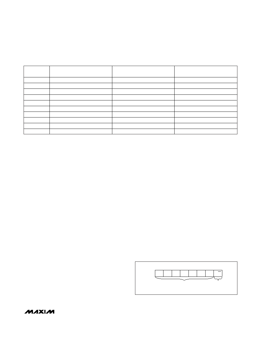
Slave Address Byte and Address Pin
The slave address byte consists of a 7-bit slave
address plus a R/W bit (see Figure 5). The DS3510’s
slave address is determined by the state of the A0 pin.
This pin allows up to two devices to reside on the same
I2C bus. Connecting A0 to GND results in a 0 in the cor-
responding bit position in the slave address.
Conversely, connecting A0 to VCC results in a 1 in the
corresponding bit position. For example, the DS3510’s
slave address byte is C0h when A0 is grounded. I2C
communication is described in detail in the
I2C Serial
Interface Description section.
SETTING
(HEX)
VCOM OUTPUT VOLTAGE
GM1–GM5 OUTPUT VOLTAGE
GM6–GM10 OUTPUT VOLTAGE
00h
VRL
GLL
GHM + (255/256) x (GHH - GHM)
01h
VRL + (1/255) x (VRH - VRL)
GLL + (1/256) x (GLM - GLL)
GHM + (254/256) x (GHH - GHM)
02h
VRL + (2/255) x (VRH - VRL)
GLL + (2/256) x (GLM - GLL)
GHM + (253/256) x (GHH - GHM)
03h
VRL + (3/255) x (VRH - VRL)
GLL + (3/256) x (GLM - GLL)
GHM + (252/256) x (GHH - GHM)
0Fh
VRL + (15/255) x (VRH - VRL)
GLL + (15/256) x (GLM - GLL)
GHM + (240/256) x (GHH - GHM)
3Fh
VRL + (63/255) x (VRH - VRL)
GLL + (63/256) x (GLM - GLL)
GHM + (192/256) x (GHH - GHM)
7Fh
VRL + (127/255) x (VRH - VRL)
GLL + (127/256) x (GLM - GLL)
GHM + (128/256) x (GHH - GHM)
FDh
VRL + (253/255) x (VRH - VRL)
GLL + (253/256) x (GLM - GLL)
GHM + (2/256) x (GHH - GHM)
FEh
VRL + (254/255) x (VRH - VRL)
GLL + (254/256) x (GLM - GLL)
GHM + (1/256) x (GHH - GHM)
FFh
VRH
GLL + (255/256) x (GLM - GLL)
GHM
Table 3. DAC Voltage/Data Relationship for Selected Codes
1
0
R/W
A0
0
MSB
LSB
SLAVE ADDRESS*
*THE SLAVE ADDRESS IS DETERMINED BY ADDRESS PIN A0.
Figure 5. DS3510 Slave Address Byte
相关PDF资料 |
PDF描述 |
|---|---|
| DS3514T+T&R | IC I2C GAMMA/VCOM BUFF 48-TQFN |
| EL1881CS-T13 | IC VIDEO SYNC SEPARATOR 8-SOIC |
| EL1883IS-T13 | IC VID SYNC SEPARATOR HORZ 8SOIC |
| EL2250CS-T13 | IC OP AMP DUAL 125MHZ 8-SOIC |
| EL4093CSZ-T7 | IC VIDEO AMP 300MHZ 16-SOIC |
相关代理商/技术参数 |
参数描述 |
|---|---|
| DS3510T+ | 功能描述:LCD Gamma缓冲器 I2C Gamma & VCOM Buffer w/EEPROM RoHS:否 制造商:Maxim Integrated 输入补偿电压: 转换速度: 电源电压-最大:20 V 电源电压-最小:9 V 电源电流: 最大功率耗散: 最大工作温度:+ 85 C 安装风格:SMD/SMT 封装 / 箱体:TQFN-38 封装:Tube |
| DS3510T+T&R | 制造商:Maxim Integrated Products 功能描述: 制造商:Maxim Integrated Products 功能描述:10 CH GAMMA+VCOM 8BIT 48 TQFN T&R L - Tape and Reel 制造商:Maxim Integrated Products 功能描述:IC I2C GAMMA/VCOM BUFF 48-TQFN |
| DS3510T+T&R | 功能描述:LCD Gamma缓冲器 I2C Gamma & VCOM Buffer w/EEPROM RoHS:否 制造商:Maxim Integrated 输入补偿电压: 转换速度: 电源电压-最大:20 V 电源电压-最小:9 V 电源电流: 最大功率耗散: 最大工作温度:+ 85 C 安装风格:SMD/SMT 封装 / 箱体:TQFN-38 封装:Tube |
| DS3510T+TR | 制造商:MAXIM 制造商全称:Maxim Integrated Products 功能描述:I2C Gamma and VCOM Buffer with EEPROM |
| DS3511MP000 | 制造商:Thomas & Betts 功能描述:30A,PLG,4P5W,MG,511,220/115V |
发布紧急采购,3分钟左右您将得到回复。