- 您现在的位置:买卖IC网 > PDF目录1916 > DS3905U-020 (Maxim Integrated Products)IC POT NV TRIPLE 128POS 10-USOP PDF资料下载
参数资料
| 型号: | DS3905U-020 |
| 厂商: | Maxim Integrated Products |
| 文件页数: | 9/11页 |
| 文件大小: | 0K |
| 描述: | IC POT NV TRIPLE 128POS 10-USOP |
| 产品培训模块: | Lead (SnPb) Finish for COTS Obsolescence Mitigation Program |
| 标准包装: | 50 |
| 接片: | 128 |
| 电阻(欧姆): | 20k |
| 电路数: | 3 |
| 温度系数: | 标准值 123 ppm/°C |
| 存储器类型: | 非易失 |
| 接口: | I²C(设备位址) |
| 电源电压: | 2.7 V ~ 5.5 V |
| 工作温度: | -40°C ~ 85°C |
| 安装类型: | 表面贴装 |
| 封装/外壳: | 10-TFSOP,10-MSOP(0.118",3.00mm 宽) |
| 供应商设备封装: | 10-µMAX |
| 包装: | 管件 |
DS3904/DS3905
Detailed Description
The DS3904/DS3905 contain three, 128-position, NV,
low temperature coefficient, variable digital resistors. All
three resistors also feature a Hi-Z function. The variable
resistor registers (F8h, F9h, and FAh) are factory pro-
grammed with a default value of 7Fh. They are con-
trolled through a 2-wire serial interface, and can serve
as a low-cost replacement for designs using conven-
tional trimming resistors. Furthermore, the DS3904
address pin (A0) allows two DS3904s to be placed on
the same 2-wire bus. The three address pins on the
DS3905 allow up to eight DS3905s to be placed on the
same 2-wire bus.
With their low cost and small size, the DS3904/DS3905
are well tailored to replace larger mechanical trimming
variable resistors. This allows the automation of calibra-
tion in many instances because the 2-wire interface can
easily be adjusted by test/production equipment.
Variable Resistor Memory Organization
The variable resistors of the DS3904/DS3905 are
addressed by communicating with the registers in
Table 1.
Using the Resistor as a Switch
By taking advantage of the high-impedance mode, a
switch can be created to produce a digital output.
Setting a resistor register to 00h creates the low state.
Writing 80h into the same resistor register enables the
high-impedance state. When used with an external
pullup resistor, such as a 4.7k
Ω pullup, a high state
is generated.
Device Operation
Clock and Data Transitions
The SDA pin is normally pulled high with an external
resistor or device. Data on the SDA pin can only change
during SCL low time periods. Data changes during SCL
high periods indicate a start or stop condition depend-
ing on the conditions discussed below. See the timing
diagrams for further details (Figures 2 and 3).
Start Condition
A high-to-low transition of SDA with SCL high is a start
condition, which must precede any other command. See
the timing diagrams for further details (Figures 2 and 3).
Stop Condition
A low-to-high transition of SDA with SCL high is a stop
condition. After a read or write sequence, the stop com-
mand places the DS3904/DS3905 into a low-power
mode. See the timing diagrams for further details
(Figures 2 and 3).
Acknowledge
All address and data bytes are transmitted through a
serial protocol. The DS3904/DS3905 pull the SDA line
low during the ninth clock pulse to acknowledge that
they have received each byte.
Standby Mode
The DS3904/DS3905 feature a low-power mode that is
automatically enabled after power-on, after a stop com-
mand, and after the completion of all internal operations.
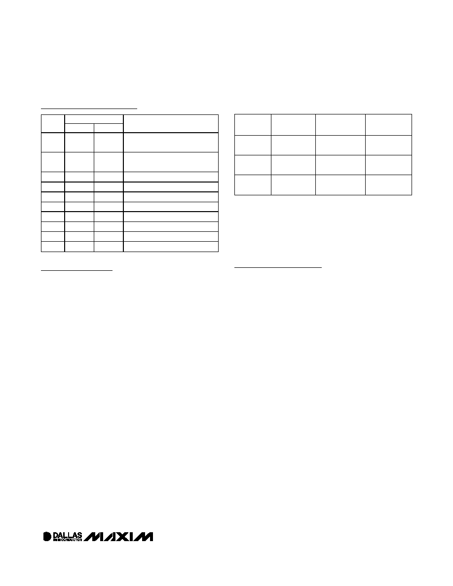
Pin Description
PIN
NAME
DS3904
DS3905
DESCRIPTION
SDA
1
2
2-Wire Serial Data. Open-drain
input/output for 2-wire data.
SCL
2
3
2-Wire Serial Clock. Input for
2-wire clock.
VCC
3
4
Supply Voltage Terminal
GND
4
5
Ground Terminal
H2
5
6
Resistor 2 High Terminals
H1
6
7
Resistor 1 High Terminals
H0
7
8
Resistor 0 High Terminals
A0
8
9
Address-Select Pin
A1
—
1
Address-Select Pin (DS3905 Only)
A2
—
10
Address-Select Pin (DS3905 Only)
Triple 128-Position Nonvolatile Digital
Variable Resistor/Switch
_____________________________________________________________________
7
Table 1. Variable Resistor Registers
ADDRESS
VARIABLE
RESISTOR
POSITION 7Fh
RESISTANCE
NUMBER OF
POSITIONS*
F8h
Resistor 0
20k
(nominal)
128 (00h to
7Fh) + Hi-Z
F9h
Resistor 1
20k
or 10k
(nominal)
128 (00h to
7Fh) + Hi-Z
FAh
Resistor 2
20k
(nominal)
128 (00h to
7Fh) + Hi-Z
*
Writing a value greater than 7Fh to any of the resistor registers
sets the high-impedance mode control bit (RHIZ, the MSB of
the resistor register) resulting in the resistor going into high-
impedance mode. Position 0 is the minimum position. Position
7Fh is the maximum position.
相关PDF资料 |
PDF描述 |
|---|---|
| DS3906U+T&R | IC RESIST VAR TRPL 10USOP |
| DS3908N+T&R | IC POT DUAL DIGITAL 14-TDFN |
| DS3930E | IC POT NV HEX I/O MEM 20-TSSOP |
| DS4301Z-200 | IC POT DIG NV 200K 32POS 8-SOIC |
| DS4520E+TRL | IC I/O EXPANDER I2C 9B 16TSSOP |
相关代理商/技术参数 |
参数描述 |
|---|---|
| DS3905U-020/T&R | 制造商:Maxim Integrated Products 功能描述:TRIPLE NV DIG RES T&R - Tape and Reel |
| DS3905U-020/T&R | 功能描述:数字电位计 IC RoHS:否 制造商:Maxim Integrated 电阻:200 Ohms 温度系数:35 PPM / C 容差:25 % POT 数量:Dual 每 POT 分接头:256 弧刷存储器:Volatile 缓冲刷: 数字接口:Serial (3-Wire, SPI) 描述/功能:Dual Volatile Low Voltage Linear Taper Digital Potentiometer 工作电源电压:1.7 V to 5.5 V 电源电流:27 uA 最大工作温度:+ 125 C 安装风格:SMD/SMT 封装 / 箱体:TQFN-16 封装:Reel |
| DS3905U-020+ | 功能描述:数字电位计 IC Triple 128-Position Nonvolatile RoHS:否 制造商:Maxim Integrated 电阻:200 Ohms 温度系数:35 PPM / C 容差:25 % POT 数量:Dual 每 POT 分接头:256 弧刷存储器:Volatile 缓冲刷: 数字接口:Serial (3-Wire, SPI) 描述/功能:Dual Volatile Low Voltage Linear Taper Digital Potentiometer 工作电源电压:1.7 V to 5.5 V 电源电流:27 uA 最大工作温度:+ 125 C 安装风格:SMD/SMT 封装 / 箱体:TQFN-16 封装:Reel |
| DS3905U-020+T&R | 制造商:Maxim Integrated Products 功能描述:DGTL POTENTIOMETER 128POS 20KOHM TRIPLE 10USOP - Tape and Reel 制造商:Maxim Integrated Products 功能描述:IC POT NV TRIPLE 128POS 10-USOP 制造商:Maxim Integrated Products 功能描述:Digital Potentiometer ICs Triple 128-Position Nonvolatile |
| DS3905U-020+T&R | 功能描述:数字电位计 IC Triple 128-Position Nonvolatile RoHS:否 制造商:Maxim Integrated 电阻:200 Ohms 温度系数:35 PPM / C 容差:25 % POT 数量:Dual 每 POT 分接头:256 弧刷存储器:Volatile 缓冲刷: 数字接口:Serial (3-Wire, SPI) 描述/功能:Dual Volatile Low Voltage Linear Taper Digital Potentiometer 工作电源电压:1.7 V to 5.5 V 电源电流:27 uA 最大工作温度:+ 125 C 安装风格:SMD/SMT 封装 / 箱体:TQFN-16 封装:Reel |
发布紧急采购,3分钟左右您将得到回复。