- 您现在的位置:买卖IC网 > PDF目录97870 > DS80C390-FCR (MAXIM INTEGRATED PRODUCTS INC) 8-BIT, MROM, 100 MHz, MICROCONTROLLER, PQFP64 PDF资料下载
参数资料
| 型号: | DS80C390-FCR |
| 厂商: | MAXIM INTEGRATED PRODUCTS INC |
| 元件分类: | Microcontroller |
| 英文描述: | 8-BIT, MROM, 100 MHz, MICROCONTROLLER, PQFP64 |
| 封装: | LQFP-64 |
| 文件页数: | 38/54页 |
| 文件大小: | 2030K |
| 代理商: | DS80C390-FCR |
第1页第2页第3页第4页第5页第6页第7页第8页第9页第10页第11页第12页第13页第14页第15页第16页第17页第18页第19页第20页第21页第22页第23页第24页第25页第26页第27页第28页第29页第30页第31页第32页第33页第34页第35页第36页第37页当前第38页第39页第40页第41页第42页第43页第44页第45页第46页第47页第48页第49页第50页第51页第52页第53页第54页
DS80C390 Dual CAN High-Speed Microprocessor
43 of 54
The SCON0 register provides control for serial port 0 while its I/O buffer is SBUF0. The registers SCON1 and
SBUF1 provide the same functions for the second serial port. A full description of the use and operation of both
serial ports can be found in the High-Speed Microcontroller User’s Guide: DS80C390 Supplement.
WATCHDOG TIMER
The watchdog is a free-running, programmable timer that can set a flag, cause an interrupt, and/or reset the
microcontroller if allowed to reach a preselected timeout. It can be restarted by software.
A typical application uses the watchdog timer as a reset source to prevent software from losing control. The
watchdog timer is initialized, selecting the timeout period and enabling the reset and/or interrupt functions. After
enabling the reset function, software must then restart the timer before its expiration or the hardware will reset the
CPU. In this way, if the code execution goes awry and software does not reset the watchdog as scheduled, the
processor is put in a known good state: reset.
Software can select one of four timeout values as controlled by the WD1 and WD0 bits. Timeout values are precise
since they are a function of the crystal frequency. When the watchdog times out, it sets the watchdog timer-reset
flag (WTRF = WDCON.2), which generates a reset if enabled by the enable watchdog-timer reset (EWT =
WDCON.1) bit. Both the enable watchdog-timer reset and the reset watchdog timer control bits are protected by
timed-access circuitry. This prevents errant software from accidentally clearing or disabling the watchdog.
The watchdog interrupt is useful for systems that do not require a reset circuit. It set the WDIF (watchdog interrupt)
flag 512 clocks before setting the reset flag. Software can optionally enable this interrupt source, which is
independent of the watchdog-reset function. The interrupt is commonly used during the debug process to
determine where watchdog-reset commands must be located in the application software. The interrupt also can
serve as a convenient time base generator or can wake up the processor from power-saving modes.
The clock control (CKCON) and the watchdog control (WDCON) SFRs control the watchdog timer. CKCON.7 and
CKCON.6 (WD1 and WD0, respectively) select the watchdog timeout period. Of course, the 4X/
2X (PMR.3) and
CD1:0 (PMR.7:6) system clock-control bits also affect the timeout period. Table 12 shows the timeout selection.
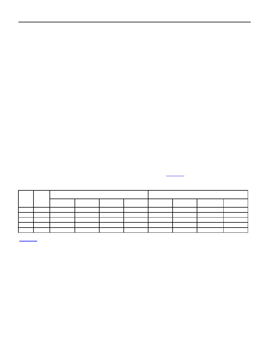
Table 12. Watchdog Timeout Values
WATCHDOG INTERRUPT TIMEOUT
WATCHDOG RESET TIMEOUT
4X/
2X CD1:0
WD1:0 = 00 WD1:0 = 01 WD1:0 = 10 WD1:0 = 11 WD1:0 = 00 WD1:0 = 01 WD1:0 = 10 WD1:0 = 11
1
00
2
15
2
18
2
21
2
24
2
15+512
2
18+512
2
21+512
2
24+512
0
00
2
16
2
19
2
22
2
25
2
16+512
2
19+512
2
22+512
2
25+512
x
01
2
17
2
20
2
23
2
26
2
17+512
2
20+512
2
23+512
2
26+512
x
10
2
17
2
20
2
23
2
26
2
17+512
2
20+512
2
23+512
2
26+512
x
11
2
25
2
28
2
31
2
34
2
25+512
2
28+512
2
31+512
2
34+512
Table 12 demonstrates that for a 33MHz crystal frequency, the watchdog timer can produce timeout periods from
3.97ms (2
17 x 1/33MHz) to over 2 seconds (2.034 = 226 x 1/33MHz) with the default setting of CD1:0 (=10). This
wide variation in timeout periods allows very flexible system implementation.
In a typical initialization, the user selects one of the possible counter values to determine the timeout. Once the
counter chain has completed a full count, hardware sets the interrupt flag (WDIF = WDCON.3). Regardless of
whether the software makes use of this flag, there are then 512 clocks left until the reset flag (WTRF = WDCON.2)
is set. Software can enable (1) or disable (0) the reset using the enable watchdog-timer-reset (EWT = WDCON.1)
bit.
相关PDF资料 |
PDF描述 |
|---|---|
| DS80C390-QCR | 8-BIT, MROM, 100 MHz, MICROCONTROLLER, PQCC68 |
| DS80C390-QNR | 8-BIT, 40 MHz, MICROCONTROLLER, PQCC68 |
| DS80C390-FNR | 8-BIT, 40 MHz, MICROCONTROLLER, PQFP64 |
| DS80CH11 | 8-BIT, MICROCONTROLLER, PQFP128 |
| DS83C530-ENL | 8-BIT, OTPROM, 33 MHz, MICROCONTROLLER, PQFP52 |
相关代理商/技术参数 |
参数描述 |
|---|---|
| DS80C390-FCR+ | 功能描述:8位微控制器 -MCU Dual CAN High-Speed RoHS:否 制造商:Silicon Labs 核心:8051 处理器系列:C8051F39x 数据总线宽度:8 bit 最大时钟频率:50 MHz 程序存储器大小:16 KB 数据 RAM 大小:1 KB 片上 ADC:Yes 工作电源电压:1.8 V to 3.6 V 工作温度范围:- 40 C to + 105 C 封装 / 箱体:QFN-20 安装风格:SMD/SMT |
| DS80C390-FNR | 功能描述:8位微控制器 -MCU Dual CAN High-Speed RoHS:否 制造商:Silicon Labs 核心:8051 处理器系列:C8051F39x 数据总线宽度:8 bit 最大时钟频率:50 MHz 程序存储器大小:16 KB 数据 RAM 大小:1 KB 片上 ADC:Yes 工作电源电压:1.8 V to 3.6 V 工作温度范围:- 40 C to + 105 C 封装 / 箱体:QFN-20 安装风格:SMD/SMT |
| DS80C390-FNR+ | 功能描述:8位微控制器 -MCU Dual CAN High-Speed RoHS:否 制造商:Silicon Labs 核心:8051 处理器系列:C8051F39x 数据总线宽度:8 bit 最大时钟频率:50 MHz 程序存储器大小:16 KB 数据 RAM 大小:1 KB 片上 ADC:Yes 工作电源电压:1.8 V to 3.6 V 工作温度范围:- 40 C to + 105 C 封装 / 箱体:QFN-20 安装风格:SMD/SMT |
| DS80C390-QCR | 功能描述:8位微控制器 -MCU Dual CAN High-Speed RoHS:否 制造商:Silicon Labs 核心:8051 处理器系列:C8051F39x 数据总线宽度:8 bit 最大时钟频率:50 MHz 程序存储器大小:16 KB 数据 RAM 大小:1 KB 片上 ADC:Yes 工作电源电压:1.8 V to 3.6 V 工作温度范围:- 40 C to + 105 C 封装 / 箱体:QFN-20 安装风格:SMD/SMT |
| DS80C390-QCR+ | 功能描述:8位微控制器 -MCU Dual CAN High-Speed RoHS:否 制造商:Silicon Labs 核心:8051 处理器系列:C8051F39x 数据总线宽度:8 bit 最大时钟频率:50 MHz 程序存储器大小:16 KB 数据 RAM 大小:1 KB 片上 ADC:Yes 工作电源电压:1.8 V to 3.6 V 工作温度范围:- 40 C to + 105 C 封装 / 箱体:QFN-20 安装风格:SMD/SMT |
发布紧急采购,3分钟左右您将得到回复。