- 您现在的位置:买卖IC网 > PDF目录16593 > EVAL-AD5235SDZ (Analog Devices Inc)BOARD EVAL FOR AD5235 PDF资料下载
参数资料
| 型号: | EVAL-AD5235SDZ |
| 厂商: | Analog Devices Inc |
| 文件页数: | 13/32页 |
| 文件大小: | 0K |
| 描述: | BOARD EVAL FOR AD5235 |
| 标准包装: | 1 |
| 主要目的: | 数字电位器 |
| 嵌入式: | 否 |
| 已用 IC / 零件: | AD5235 |
| 主要属性: | 2 沟道,1024 位置 |
| 次要属性: | SPI 接口 |
| 已供物品: | 板,CD |
第1页第2页第3页第4页第5页第6页第7页第8页第9页第10页第11页第12页当前第13页第14页第15页第16页第17页第18页第19页第20页第21页第22页第23页第24页第25页第26页第27页第28页第29页第30页第31页第32页
AD5235
Data Sheet
Rev. F | Page 20 of 32
ADVANCED CONTROL MODES
The AD5235 digital potentiometer includes a set of user
programming features to address the wide number of
applications for these universal adjustment devices.
Key programming features include the following:
Scratchpad programming to any desirable values
Nonvolatile memory storage of the scratchpad RDAC
register value in the EEMEM register
Increment and decrement instructions for the RDAC
wiper register
Left and right bit shift of the RDAC wiper register to
achieve ±6 dB level changes
26 extra bytes of user-addressable nonvolatile memory
Linear Increment and Decrement Instructions
The increment and decrement instructions (Instruction 14,
Instruction 15, Instruction 6, and Instruction 7) are useful for
linear step adjustment applications. These commands simplify
microcontroller software coding by allowing the controller to
send just an increment or decrement command to the device.
The adjustment can be individual or in a ganged potentiometer
arrangement where both wiper positions are changed at the
same time.
For an increment command, executing Instruction 14
automatically moves the wiper to the next resistance segment
position. The master increment command, Instruction 15,
moves all resistor wipers up by one position.
Logarithmic Taper Mode Adjustment
Four programming instructions produce logarithmic taper
increment and decrement of the wiper position control by
an individual potentiometer or by a ganged potentiometer
arrangement where both wiper positions are changed at the
same time. The 6 dB increment is activated by Instruction 12
and Instruction 13, and the 6 dB decrement is activated by
Instruction 4 and Instruction 5. For example, starting with the
wiper connected to Terminal B, executing 11 increment
instructions (Command Instruction 12) moves the wiper in 6 dB
steps from 0% of the RAB (Terminal B) position to 100% of the RAB
position of the AD5235 10-bit potentiometer. When the wiper
position is near the maximum setting, the last 6 dB increment
instruction causes the wiper to go to the full-scale 1023 code
position. Further 6 dB per increment instructions do not
change the wiper position beyond its full scale (see Table 8).
The 6 dB step increments and 6 dB step decrements are achieved
by shifting the bit internally to the left or right, respectively. The
following information explains the nonideal ±6 dB step adjustment
under certain conditions. Table 8 illustrates the operation of the
shifting function on the RDAC register data bits. Each table row
represents a successive shift operation. Note that the left-shift
12 and 13 instructions were modified such that, if the data in
the RDAC register is equal to zero and the data is shifted left,
the RDAC register is then set to Code 1. Similarly, if the data in
the RDAC register is greater than or equal to midscale and the data
is shifted left, then the data in the RDAC register is automatically
set to full scale. This makes the left-shift function as ideal a
logarithmic adjustment as possible.
The Right-Shift 4 instruction and Right-Shift 5 instruction are
ideal only if the LSB is 0 (ideal logarithmic = no error). If the
LSB is 1, the right-shift function generates a linear half-LSB
error, which translates to a number-of-bits dependent logarithmic
error, as shown in Figure 44. Figure 44 shows the error of the odd
numbers of bits for the AD5235.
Table 8. Detail Left-Shift and Right-Shift Functions for 6 dB
Step Increment and Decrement
Left-Shift (+6 dB/Step)
Right-Shift(–6 dB/Step)
00 0000 0000
11 1111 1111
00 0000 0001
01 1111 1111
00 0000 0010
00 1111 1111
00 0000 0100
00 0111 1111
00 0000 1000
00 0011 1111
00 0001 0000
00 0001 1111
00 0010 0000
00 0000 1111
00 0100 0000
00 0000 0111
00 1000 0000
00 0000 0011
01 0000 0000
00 0000 0001
10 0000 0000
00 0000 0000
11 1111 1111
00 0000 0000
11 1111 1111
00 0000 0000
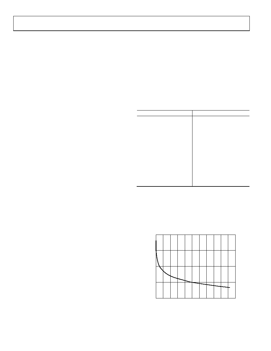
Actual conformance to a logarithmic curve between the data
contents in the RDAC register and the wiper position for each
Right-Shift 4 command and Right-Shift 5 command execution
contains an error only for odd numbers of bits. Even numbers of
bits are ideal. Figure 44 shows plots of log error [20 × log10
(error/code)] for the AD5235. For example, Code 3 log error = 20 ×
log10 (0.5/3) = 15.56 dB, which is the worst case. The log error plot
is more significant at the lower codes (see Figure 44).
CODE (From 1 to 1023 by 2.0 × 103)
0
G
AI
N
(
d
B)
0.1
0.2
0.3
0.4
0.5
0.6
0.7
0.8
0.9
1.0
1.1
02816-
043
0
–40
–20
–60
–80
Figure 44. Log Error Conformance for Odd Numbers of Bits Only
(Even Numbers of Bits Are Ideal)
相关PDF资料 |
PDF描述 |
|---|---|
| MCZ33742EGR2 | IC SYSTEM BASIS CHIP CAN 28-SOIC |
| ECM30DCAN | CONN EDGECARD 60POS R/A .156 SLD |
| EVAL-ADCMP561BRQZ | BOARD EVALUATION ADCMP561BRQZ |
| VI-BNB-EW | CONVERTER MOD DC/DC 95V 100W |
| A3AAB-2036M | IDC CABLE- ASC20B/AE20M/ASC20B |
相关代理商/技术参数 |
参数描述 |
|---|---|
| EVAL-AD5235SDZ | 制造商:Analog Devices 功能描述:Evaluation board |
| EVAL-AD5242EBZ | 功能描述:BOARD EVALUATION FOR AD5242 RoHS:是 类别:编程器,开发系统 >> 评估演示板和套件 系列:- 标准包装:1 系列:- 主要目的:电信,线路接口单元(LIU) 嵌入式:- 已用 IC / 零件:IDT82V2081 主要属性:T1/J1/E1 LIU 次要属性:- 已供物品:板,电源,线缆,CD 其它名称:82EBV2081 |
| EVAL-AD5243SDZ | 功能描述:BOARD EVAL FOR AD5243 RoHS:是 类别:编程器,开发系统 >> 评估演示板和套件 系列:* 标准包装:1 系列:- 主要目的:电信,线路接口单元(LIU) 嵌入式:- 已用 IC / 零件:IDT82V2081 主要属性:T1/J1/E1 LIU 次要属性:- 已供物品:板,电源,线缆,CD 其它名称:82EBV2081 |
| EVAL-AD5245EBZ | 功能描述:EVAL BOARD FOR AD5245 RoHS:是 类别:编程器,开发系统 >> 评估演示板和套件 系列:- 标准包装:1 系列:- 主要目的:电信,线路接口单元(LIU) 嵌入式:- 已用 IC / 零件:IDT82V2081 主要属性:T1/J1/E1 LIU 次要属性:- 已供物品:板,电源,线缆,CD 其它名称:82EBV2081 |
| EVAL-AD5246DBZ | 功能描述:BOARD EVAL FOR AD5246DBZ RoHS:否 类别:编程器,开发系统 >> 评估演示板和套件 系列:* 标准包装:1 系列:- 主要目的:电信,线路接口单元(LIU) 嵌入式:- 已用 IC / 零件:IDT82V2081 主要属性:T1/J1/E1 LIU 次要属性:- 已供物品:板,电源,线缆,CD 其它名称:82EBV2081 |
发布紧急采购,3分钟左右您将得到回复。