- 您现在的位置:买卖IC网 > PDF目录17079 > EVAL-AD5421SDZ (Analog Devices Inc)BOARD EVAL FOR AD5421 PDF资料下载
参数资料
| 型号: | EVAL-AD5421SDZ |
| 厂商: | Analog Devices Inc |
| 文件页数: | 14/36页 |
| 文件大小: | 0K |
| 描述: | BOARD EVAL FOR AD5421 |
| 标准包装: | 1 |
| DAC 的数量: | 1 |
| 位数: | 16 |
| 数据接口: | 串行,SPI? |
| 设置时间: | 50µs |
| DAC 型: | 电压 |
| 工作温度: | -40°C ~ 105°C |
| 已供物品: | 板 |
| 已用 IC / 零件: | AD5421 |
第1页第2页第3页第4页第5页第6页第7页第8页第9页第10页第11页第12页第13页当前第14页第15页第16页第17页第18页第19页第20页第21页第22页第23页第24页第25页第26页第27页第28页第29页第30页第31页第32页第33页第34页第35页第36页
Data Sheet
AD5421
Rev. G | Page 21 of 36
THEORY OF OPERATION
The AD5421 is an integrated device designed for use in loop-
powered, 4 mA to 20 mA smart transmitter applications. In a
single chip, the AD5421 provides a 16-bit DAC and current
amplifier for digital control of the loop current, a voltage
regulator to power the entire transmitter, a voltage reference,
fault alert functions, a flexible SPI-compatible serial interface,
gain and offset adjust registers, as well as other features and
functions. The features of the AD5421 are described in the
following sections.
FAULT ALERTS
The AD5421 provides a number of fault alert features. All
faults are signaled to the controller via the FAULT pin and the
fault register. In the case of a loss of communication between
programs the loop current to an alarm value. If the controller
detects that the FAULT pin is set high, it should then read the
fault register to determine the cause of the fault. Note that the
watchdog timer does not reset and restart its condition with an
alarm active. If the auto fault readback is disabled and an SPI
fault occurs, such that the watchdog timer is timed out, the
watchdog timer remains inactive until the status register is
manually read back by the user. Following this readback, the
watchdog timer resumes operation.
SPI Fault
The SPI fault is asserted if there is no valid communication to
any register of the AD5421 for more than a user-defined period.
The user can program the time period using the SPI watchdog
timeout bits of the control register. The SPI fault bit of the fault
register indicates the fault on the SPI bus. Because this fault is
caused by a loss of communication between the controller and
the AD5421, the loop current is also forced to the alarm value.
The direction of the alarm current (downscale or upscale)
is selected via the ALARM_CURRENT_DIRECTION pin.
Connecting this pin to DVDD selects an upscale alarm current
(22.8 mA/24 mA); connecting this pin to COM selects a
downscale alarm current (3.2 mA).
Packet Error Checking
To verify that data has been received correctly in noisy environ-
ments, the AD5421 offers the option of error checking based on
an 8-bit cyclic redundancy check (CRC). Packet error checking
(PEC) is enabled by writing to the AD5421 with a 32-bit serial
frame, where the least significant eight bits are the frame check
sequence (FCS). The device controlling the AD5421 should
generate the 8-bit FCS using the following polynomial:
C(x) = x 8 + x 2 + x + 1
The 8-bit FCS is appended to the end of the data-word, and
32 data bits are sent to the AD5421 before SYNC is taken high.
If the check is valid, the data is accepted. If the check fails, the
FAULT pin is asserted and the PEC bit of the fault register is set.
After the fault register is read, the PEC bit is reset low and the
FAULT pin returns low.
In the case of data readback, if the AD5421 is addressed with a
32-bit frame, it generates the 8-bit frame check sequence and
appends it to the end of the 24-bit data stream to create a 32-bit
data stream.
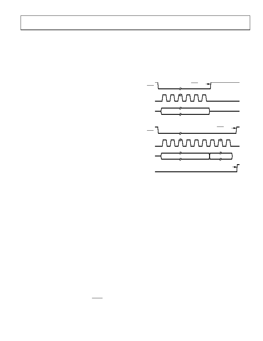
SDIN
SYNC
SCLK
UPDATE ON SYNC HIGH
MSB
D23
LSB
D0
24-BIT DATA
24-BIT DATA TRANSFER—NO ERROR CHECKING
SDIN
FAULT
SYNC
SCLK
UPDATE AFTER SYNC HIGH
ONLY IF ERROR CHECK PASSED
FAULT PIN GOES HIGH
IF ERROR CHECK FAILS
MSB
D31
LSB
D8
D7
D0
24-BIT DATA
8-BIT FCS
32-BIT DATA TRANSFER WITH ERROR CHECKING
09128-
049
Figure 41. PEC Timing
Current Loop Fault
The current loop (ILOOP) fault is asserted when the actual loop
current is not within ±0.01% FSR of the programmed loop
current. If the measured loop current is less than the programmed
loop current, the ILOOP Under bit of the fault register is set. If the
measured loop current is greater than the programmed loop
current, the ILOOP Over bit of the fault register is set. The FAULT
pin is set to logic high in either case.
An ILOOP Over condition occurs when the value of the load current
or DVDD) is greater than the loop current that is programmed
to flow in the loop. An ILOOP under condition occurs when there
is insufficient compliance voltage to support the programmed
loop current, caused by excessive load resistance or low loop
supply voltage.
Overtemperature Fault
There are two overtemperature alert bits in the fault register:
Temp 100°C and Temp 140°C. If the die temperature of the
AD5421 exceeds either 100°C or 140°C, the appropriate bit is
set. If the Temp 140°C bit is set in the fault register, the FAULT
pin is set to logic high.
相关PDF资料 |
PDF描述 |
|---|---|
| NR6028T150M | INDUCTOR 15UH 1.8A 20% SMD |
| SC53LC-6R8 | INDUCTOR SMD 6.8UH 1.51A 100KHZ |
| V48C2E50BL3 | CONVERTER MOD DC/DC 2V 50W |
| 0210490844 | CABLE JUMPER 1.25MM .178M 15POS |
| GBC05DREI-S734 | CONN EDGECARD 10POS .100 EYELET |
相关代理商/技术参数 |
参数描述 |
|---|---|
| EVAL-AD5422EBZ | 功能描述:BOARD EVAL FOR AD5422 RoHS:是 类别:编程器,开发系统 >> 评估板 - 数模转换器 (DAC) 系列:- 产品培训模块:Lead (SnPb) Finish for COTS Obsolescence Mitigation Program 标准包装:1 系列:- DAC 的数量:4 位数:12 采样率(每秒):- 数据接口:串行,SPI? 设置时间:3µs DAC 型:电流/电压 工作温度:-40°C ~ 85°C 已供物品:板 已用 IC / 零件:MAX5581 |
| EVAL-AD5422LFEBZ | 功能描述:BOARD EVAL FOR AD5422LFEBZ RoHS:否 类别:编程器,开发系统 >> 评估板 - 数模转换器 (DAC) 系列:* 产品培训模块:Lead (SnPb) Finish for COTS Obsolescence Mitigation Program 标准包装:1 系列:- DAC 的数量:4 位数:12 采样率(每秒):- 数据接口:串行,SPI? 设置时间:3µs DAC 型:电流/电压 工作温度:-40°C ~ 85°C 已供物品:板 已用 IC / 零件:MAX5581 |
| EVAL-AD5424EB | 制造商:Analog Devices 功能描述:EVALUATION BOARD I.C. - Bulk 制造商:Rochester Electronics LLC 功能描述: |
| EVAL-AD5424EBZ | 功能描述:BOARD EVALUATION FOR AD5424 RoHS:是 类别:编程器,开发系统 >> 评估板 - 数模转换器 (DAC) 系列:- 产品培训模块:Lead (SnPb) Finish for COTS Obsolescence Mitigation Program 标准包装:1 系列:- DAC 的数量:4 位数:12 采样率(每秒):- 数据接口:串行,SPI? 设置时间:3µs DAC 型:电流/电压 工作温度:-40°C ~ 85°C 已供物品:板 已用 IC / 零件:MAX5581 |
| EVAL-AD5425EB | 制造商:Analog Devices 功能描述:EVALUATION BOARD I.C. - Bulk |
发布紧急采购,3分钟左右您将得到回复。