- 您现在的位置:买卖IC网 > PDF目录16601 > EVAL-AD5933EBZ (Analog Devices Inc)BOARD EVALUATION FOR AD5933 PDF资料下载
参数资料
| 型号: | EVAL-AD5933EBZ |
| 厂商: | Analog Devices Inc |
| 文件页数: | 13/40页 |
| 文件大小: | 0K |
| 描述: | BOARD EVALUATION FOR AD5933 |
| 产品培训模块: | AD5933 Impedance to Digital Converter ADP2102 DSP Battery Life Applications Direct Digital Synthesis Tutorial Series (1 of 7): Introduction Direct Digital Synthesizer Tutorial Series (7 of 7): DDS in Action Direct Digital Synthesis Tutorial Series (3 of 7): Angle to Amplitude Converter Direct Digital Synthesis Tutorial Series (6 of 7): SINC Envelope Correction Direct Digital Synthesis Tutorial Series (4 of 7): Digital-to-Analog Converter Direct Digital Synthesis Tutorial Series (2 of 7): The Accumulator |
| 标准包装: | 1 |
| 主要目的: | 计时,直接数字合成(DDS) |
| 嵌入式: | 否 |
| 已用 IC / 零件: | AD5933 |
| 主要属性: | 12 位数模转换器,24 位调节字宽 |
| 次要属性: | 16MHz 2.7 V ~ 5.5 V 图形用户界面 |
| 已供物品: | 板,缆线,CD |
| 产品目录页面: | 797 (CN2011-ZH PDF) |
| 相关产品: | AD5933YRSZ-REEL7-ND - NETWORK ANALYZER 12B 1MSP 16SSOP AD5933YRSZ-ND - IC NTWK ANALYZER 12B 1MSP 16SSOP |
第1页第2页第3页第4页第5页第6页第7页第8页第9页第10页第11页第12页当前第13页第14页第15页第16页第17页第18页第19页第20页第21页第22页第23页第24页第25页第26页第27页第28页第29页第30页第31页第32页第33页第34页第35页第36页第37页第38页第39页第40页
AD5933
Data Sheet
Rev. E | Page 20 of 40
new phase (including the phase due to the impedance) using
the same formula. The phase of the unknown impedance (Z)
is given by the following formula:
)
(
system
unknown
Z
Φ
=
where:
system
is the phase of the system with a calibration resistor
connected between VIN and VOUT.
Φunknown is the phase of the system with the unknown
impedance connected between VIN and VOUT.
Z is the phase due to the impedance, that is, the impedance
phase.
Note that it is possible to calculate the gain factor and to
calibrate the system phase using the same real and imaginary
component values when a resistor is connected between the
VOUT and VIN pins of the AD5933, for example, measuring
the impedance phase (Z) of a capacitor.
The excitation signal current leads the excitation signal voltage
across a capacitor by 90 degrees. Therefore, an approximate
90 degree phase difference exists between the system phase
responses measured with a resistor and that of the system phase
responses measured with a capacitive impedance.
As previously outlined, if the user would like to determine the
phase angle of capacitive impedance (Z), the user first has to
determine the system phase response ( system
) and subtract
this from the phase calculated with the capacitor connected
between VOUT and VIN (Φunknown).
A plot showing the AD5933 system phase response calculated
using a 220 kΩ calibration resistor (RFB = 220 kΩ, PGA = ×1)
and the repeated phase measurement with a 10 pF capacitive
impedance is shown in Figure 26.
One important point to note about the phase formula used to
plot Figure 26 is that it uses the arctangent function that returns
a phase angle in radians and, therefore, it is necessary to convert
from radians to degrees.
200
180
160
140
120
100
80
60
40
20
0
15k
30k
45k
60k
75k
90k
105k
120k
FREQUENCY (Hz)
SYST
EM
PH
A
SE
(D
e
g
re
e
s
)
05324-
032
220k RESISTOR
10pF CAPACITOR
Figure 26. System Phase Response vs. Capacitive Phase
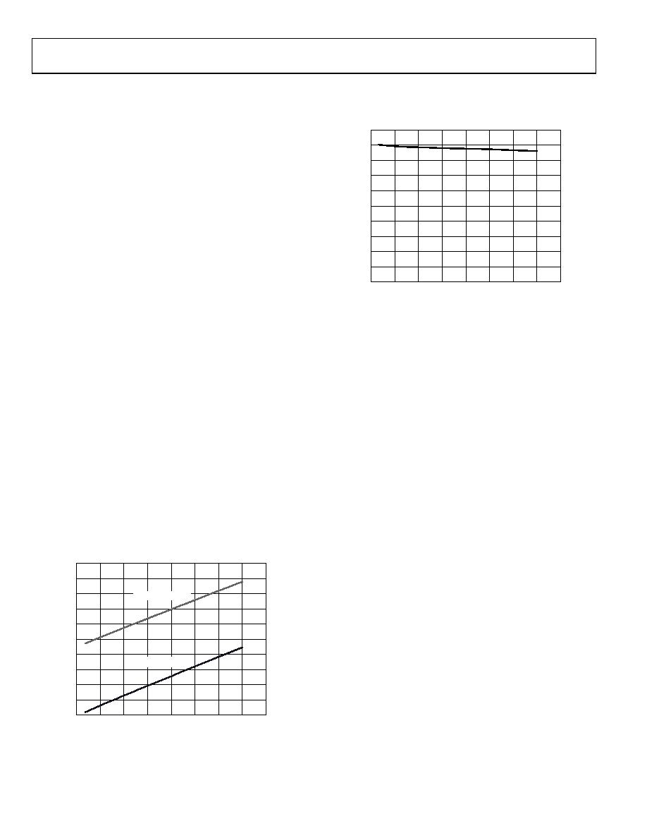
The phase difference (that is, Z) between the phase response
of a capacitor and the system phase response using a resistor is
the impedance phase of the capacitor, Z (see Figure 27).
–100
–90
–80
–70
–60
–50
–40
–30
–20
–10
0
15k
30k
45k
60k
75k
90k
105k
120k
FREQUENCY (Hz)
P
HAS
E
(
Deg
rees)
05324-
033
Figure 27. Phase Response of a Capacitor
Also when using the real and imaginary values to interpret
the phase at each measurement point, take care when using
the arctangent formula. The arctangent function returns the
correct standard phase angle only when the sign of the real and
imaginary values are positive, that is, when the coordinates lie
in the first quadrant. The standard angle is the angle taken
counterclockwise from the positive real x-axis. If the sign of the
real component is positive and the sign of the imaginary
component is negative, that is, the data lies in the second
quadrant, then the arctangent formula returns a negative angle
and it is necessary to add a further 180 degrees to calculate the
correct standard angle. Likewise, when the real and imaginary
components are both negative, that is, when the coordinates lie
in the third quadrant, then the arctangent formula returns a
positive angle and it is necessary to add 180 degrees from the
angle to return the correct standard phase. Finally, when the
real component is positive and the imaginary component is
negative, that is, the data lies in the fourth quadrant, then the
arctangent formula returns a negative angle. It is necessary to
add 360 degrees to the angle to calculate the correct phase
angle.
Therefore, the correct standard phase angle is dependent upon
the sign of the real and imaginary component and is summa-
rized in Table 7.
相关PDF资料 |
PDF描述 |
|---|---|
| VI-B2W-EW | CONVERTER MOD DC/DC 5.5V 100W |
| VI-B2V-EW | CONVERTER MOD DC/DC 5.8V 100W |
| Q2-Z-3-01-SS100FT | HEATSHRINK POLY Q2Z 3"X100FT BLK |
| GEM18DRKF | CONN EDGECARD 36POS DIP .156 SLD |
| 848407-1 | CONN LEAD ASSY SGL-END 20AWG 16" |
相关代理商/技术参数 |
参数描述 |
|---|---|
| EVAL-AD5933EBZ | 制造商:Analog Devices 功能描述:IMPEDANCE CONVERTER EVALUATION BOARD |
| EVAL-AD5934EB | 制造商:Analog Devices 功能描述:EVALUATION BOARD I.C. - Bulk |
| EVAL-AD5934EBZ | 功能描述:BOARD EVALUATION FOR AD5934 RoHS:是 类别:编程器,开发系统 >> 评估演示板和套件 系列:- 产品培训模块:Obsolescence Mitigation Program 标准包装:1 系列:- 主要目的:电源管理,电池充电器 嵌入式:否 已用 IC / 零件:MAX8903A 主要属性:1 芯锂离子电池 次要属性:状态 LED 已供物品:板 |
| EVAL-AD607EBZ | 功能描述:BOARD EVALUATION FOR AD607 RoHS:是 类别:RF/IF 和 RFID >> RF 评估和开发套件,板 系列:- 标准包装:1 系列:- 类型:GPS 接收器 频率:1575MHz 适用于相关产品:- 已供物品:模块 其它名称:SER3796 |
| EVAL-AD608EBZ | 功能描述:BOARD EVALUATION FOR AD608 RoHS:是 类别:RF/IF 和 RFID >> RF 评估和开发套件,板 系列:- 标准包装:1 系列:- 类型:GPS 接收器 频率:1575MHz 适用于相关产品:- 已供物品:模块 其它名称:SER3796 |
发布紧急采购,3分钟左右您将得到回复。