- 您现在的位置:买卖IC网 > PDF目录17044 > EVAL-AD7688SDZ (Analog Devices Inc)BOARD EVAL FOR AD7688 PDF资料下载
参数资料
| 型号: | EVAL-AD7688SDZ |
| 厂商: | Analog Devices Inc |
| 文件页数: | 8/28页 |
| 文件大小: | 0K |
| 描述: | BOARD EVAL FOR AD7688 |
| 标准包装: | 1 |
| 系列: | PulSAR® |
| ADC 的数量: | 1 |
| 位数: | 16 |
| 采样率(每秒): | 500k |
| 数据接口: | DSP,MICROWIRE?,QSPI?,串行,SPI? |
| 输入范围: | ±VREF |
| 在以下条件下的电源(标准): | 3.75mW @ 100kSPS |
| 工作温度: | -40°C ~ 85°C |
| 已用 IC / 零件: | AD7688 |
| 已供物品: | 板 |
第1页第2页第3页第4页第5页第6页第7页当前第8页第9页第10页第11页第12页第13页第14页第15页第16页第17页第18页第19页第20页第21页第22页第23页第24页第25页第26页第27页第28页
AD7688
Rev. A | Page 16 of 28
02973-
030
FREQUENCY (kHz)
10000
1
1000
10
100
P
S
RR
(
d
B)
95
90
85
80
75
70
65
60
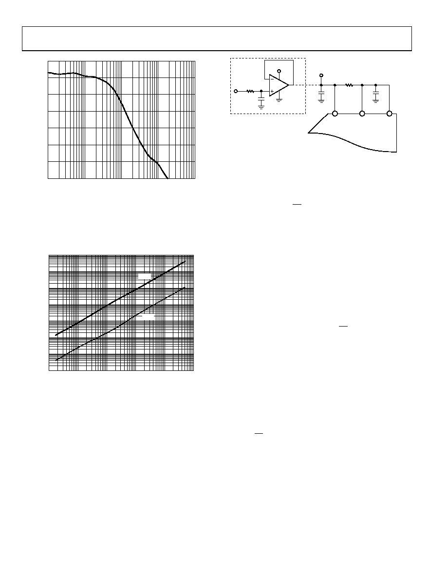
Figure 31. PSRR vs. Frequency
The AD7688 powers down automatically at the end of each
conversion phase and, therefore, the power scales linearly with
the sampling rate, as shown in Figure 32. This makes the part
ideal for low sampling rate (even a few Hz) and low battery-
powered applications.
SAMPLING RATE (SPS)
OPERATI
NG
CURRENT
(
μA)
1000
10
0.1
0.001
10
100
1000
10000
100000
1000000
02973-
031
VIO
VDD
Figure 32. Operating Currents vs. Sampling Rate
SUPPLYING THE ADC FROM THE REFERENCE
For simplified applications, the AD7688, with its low operating
current, can be supplied directly using the reference circuit
shown in Figure 33. The reference line can be driven by either:
The system power supply directly.
A reference voltage with enough current output capability,
such as the ADR43x.
A reference buffer, such as the AD8031, which can also
filter the system power supply, as shown in Figure 33.
AD8031
AD7688
VIO
REF
VDD
10
μF
1
μF
10
Ω
10k
Ω
5V
1
μF
1
02973-
032
1OPTIONAL REFERENCE BUFFER AND FILTER.
Figure 33. Example of Application Circuit
DIGITAL INTERFACE
Though the AD7688 has a reduced number of pins, it offers
flexibility in its serial interface modes.
The AD7688, when in CS mode, is compatible with SPI, QSPI,
digital hosts, and DSPs, e.g., Blackfin ADSP-BF53x or ADSP-
219x. This interface can use either 3-wire or 4-wire. A 3-wire
interface using the CNV, SCK, and SDO signals minimizes
wiring connections useful, for instance, in isolated applications.
A 4-wire interface using the SDI, CNV, SCK, and SDO signals
allows CNV, which initiates the conversions, to be independent
of the readback timing (SDI). This is useful in low jitter
sampling or simultaneous sampling applications.
The AD7688, when in chain mode, provides a daisy chain
feature using the SDI input for cascading multiple ADCs on a
single data line similar to a shift register.
The mode in which the part operates depends on the SDI level
when the CNV rising edge occurs. The CS mode is selected if
SDI is high and the chain mode is selected if SDI is low. The
SDI hold time is such that when SDI and CNV are connected
together, the chain mode is always selected.
In either mode, the AD7688 offers the flexibility to optionally
force a start bit in front of the data bits. This start bit can be
used as a BUSY signal indicator to interrupt the digital host and
trigger the data reading. Otherwise, without a BUSY indicator,
the user must time out the maximum conversion time prior to
readback.
The BUSY indicator feature is enabled as:
In the CS mode, if CNV or SDI is low when the ADC
conversion ends (
and
).
In the chain mode, if SCK is high during the CNV rising edge
相关PDF资料 |
PDF描述 |
|---|---|
| SDR0805-680KL | INDUCTOR UNSHIELD 68UH .85A SMD |
| MIC2076A-2YM | IC SW DISTRIBUTION 2CH 8SOIC |
| GEM25DTBH | CONN EDGECARD 50POS R/A .156 SLD |
| PH50S245 | CONVERTER DC/DC 5V 50W 6-PIN |
| 94SVP687X0004F8 | CAP ALUM 680UF 4V 20% SMD |
相关代理商/技术参数 |
参数描述 |
|---|---|
| EVAL-AD7689CBZ | 制造商:Analog Devices 功能描述:EVAL BOARD 8 CH 250KSPS 16BIT ADC IC - Bulk |
| EVAL-AD7689EDZ | 功能描述:BOARD EVAL AD7689 RoHS:是 类别:编程器,开发系统 >> 评估板 - 模数转换器 (ADC) 系列:PulSAR® 产品培训模块:Obsolescence Mitigation Program 标准包装:1 系列:- ADC 的数量:1 位数:12 采样率(每秒):94.4k 数据接口:USB 输入范围:±VREF/2 在以下条件下的电源(标准):- 工作温度:-40°C ~ 85°C 已用 IC / 零件:MAX11645 已供物品:板,软件 |
| EVAL-AD7689EDZ | 制造商:Analog Devices 功能描述:16 Bit A/D Converter Eval. Board |
| EVAL-AD7690CB | 制造商:Analog Devices 功能描述:AD7690 EVAL - Bulk |
| EVAL-AD7690SDZ | 功能描述:BOARD EVAL FOR AD7690 RoHS:是 类别:编程器,开发系统 >> 评估板 - 模数转换器 (ADC) 系列:PulSAR® 产品培训模块:Obsolescence Mitigation Program 标准包装:1 系列:- ADC 的数量:1 位数:12 采样率(每秒):94.4k 数据接口:USB 输入范围:±VREF/2 在以下条件下的电源(标准):- 工作温度:-40°C ~ 85°C 已用 IC / 零件:MAX11645 已供物品:板,软件 |
发布紧急采购,3分钟左右您将得到回复。