- 您现在的位置:买卖IC网 > PDF目录16598 > EVAL-AD9838SDZ (Analog Devices Inc)BOARD EVAL FOR AD9838 PDF资料下载
参数资料
| 型号: | EVAL-AD9838SDZ |
| 厂商: | Analog Devices Inc |
| 文件页数: | 14/32页 |
| 文件大小: | 0K |
| 描述: | BOARD EVAL FOR AD9838 |
| 产品培训模块: | Direct Digital Synthesis Tutorial Series (1 of 7): Introduction Direct Digital Synthesizer Tutorial Series (7 of 7): DDS in Action Direct Digital Synthesis Tutorial Series (3 of 7): Angle to Amplitude Converter Direct Digital Synthesis Tutorial Series (6 of 7): SINC Envelope Correction Direct Digital Synthesis Tutorial Series (4 of 7): Digital-to-Analog Converter Direct Digital Synthesis Tutorial Series (2 of 7): The Accumulator |
| 标准包装: | 1 |
| 主要目的: | 计时,直接数字合成(DDS) |
| 嵌入式: | 否 |
| 已用 IC / 零件: | AD9838 |
| 主要属性: | USB 供电或外部电源 |
| 次要属性: | SPI 接口 |
| 已供物品: | 板,线缆,CD,文档 |
第1页第2页第3页第4页第5页第6页第7页第8页第9页第10页第11页第12页第13页当前第14页第15页第16页第17页第18页第19页第20页第21页第22页第23页第24页第25页第26页第27页第28页第29页第30页第31页第32页
AD9838
Rev. A | Page 21 of 32
IOUT AND IOUTB PINS
SIGN BIT OUT PIN
The AD9838 offers a variety of outputs from the chip. The
digital outputs are available from the SIGN BIT OUT pin. The
available outputs are the comparator output or the MSB of the
DAC data. The bits controlling the SIGN BIT OUT pin are
listed in Table 18.
The analog outputs from the AD9838 are available from the
IOUT and IOUTB pins. The available outputs are a sinusoidal
output or a triangular output (see Table 19).
Note that the SLEEP pin and the SLEEP12 bit must be set to 0
(the DAC is enabled) when using the IOUT and IOUTB pins.
Table 18. Outputs from the SIGN BIT OUT Pin
OPBITEN
Bit
MODE
Bit
SIGN/PIB
Bit
DIV2
Bit
SIGN BIT OUT Pin
0
X
High impedance
1
0
DAC data MSB/2
1
0
1
DAC data MSB
1
0
1
0
Reserved
1
0
1
Comparator output
1
X
Reserved
Table 19. Outputs from the IOUT and IOUTB Pins
OPBITEN Bit
MODE Bit
IOUT and IOUTB Pin Output
0
Sinusoid
0
1
Triangle
1
0
Sinusoid
1
Reserved
Sinusoidal Output
The SIN ROM converts the phase information from the
frequency and phase registers into amplitude information,
resulting in a sinusoidal signal at the output. To obtain a
sinusoidal output from the IOUT and IOUTB pins, set the
MODE bit (Bit D1) to 0.
The SIGN BIT OUT pin must be enabled before use. The
OPBITEN bit (Bit D5) in the control register enables and dis-
ables this pin. When OPBITEN = 1, the SIGN BIT OUT pin is
enabled. Note that if OPBITEN = 1, the MODE bit (Bit D1) in
the control register should be set to 0.
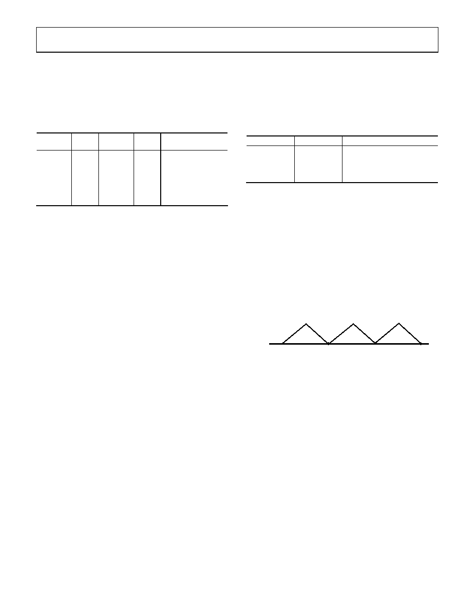
Triangle Output
Comparator Output
The SIN ROM can be bypassed so that the truncated digital output
from the NCO is sent to the DAC. In this case, the output is no
longer sinusoidal. The DAC produces a 10-bit linear triangular
function (see Figure 23). To obtain a triangle output from the
IOUT and IOUTB pins, set the MODE bit (Bit D1) to 1 and the
OPBITEN bit (Bit D5) to 0.
The AD9838 has an on-board comparator. To connect this com-
parator to the SIGN BIT OUT pin, the OPBITEN bit (Bit D5)
and the SIGN/PIB bit (Bit D4) must be set to 1. After filtering
the sinusoidal output from the DAC, the waveform can be
applied to the comparator to generate a square waveform.
MSB of the DAC Data
3π/2
7π/2
11π/2
VOUT MAX
VOUT MIN
09
07
7-
02
7
The MSB of the DAC data can be output from the AD9838.
By setting the OPBITEN bit (Bit D5) to 1 and the SIGN/PIB bit
(Bit D4) to 0, the MSB of the DAC data is available at the SIGN
BIT OUT pin. This output is useful as a coarse clock source.
The square wave can also be divided by 2 before being output.
The DIV2 bit (Bit D3) in the control register controls the
frequency of this output from the SIGN BIT OUT pin.
Figure 23. Triangle Output
POWERING UP THE AD9838
The flowchart in Figure 24 shows the operating routine for the
AD9838. When the AD9838 is powered up, the part should be
reset. This resets the appropriate internal registers to 0 to provide
an analog output of midscale. To avoid spurious DAC outputs
during AD9838 initialization, the RESET pin or the RESET bit
should be set to 1 until the part is ready to begin generating
an output.
A reset does not reset the phase, frequency, or control registers.
These registers will contain invalid data and, therefore, should
be set to known values by the user. The RESET pin or bit should
then be set to 0 to begin generating an output. The data appears
on the DAC output eight or nine MCLK cycles after the RESET
pin or bit is set to 0.
相关PDF资料 |
PDF描述 |
|---|---|
| A3AAH-2036M | IDC CABLE - ASC20H/AE20M/ASC20H |
| M1CXA-3436R | IDC CABLE - MKC34A/MC34M/X |
| M1AXA-3436R | IDC CABLE - MSC34A/MC34M/X |
| B82477R4472M100 | INDUCTOR POWER 4.7UH 7.5A SMD |
| 860529-8 | CONN LEAD ASSY DBL-END 20AWG 10" |
相关代理商/技术参数 |
参数描述 |
|---|---|
| EVAL-AD9880-ABZ | 功能描述:KIT MODULE VIDEO INPUT AD9880 RoHS:是 类别:编程器,开发系统 >> 评估演示板和套件 系列:- 标准包装:1 系列:PCI Express® (PCIe) 主要目的:接口,收发器,PCI Express 嵌入式:- 已用 IC / 零件:DS80PCI800 主要属性:- 次要属性:- 已供物品:板 |
| EVAL-ADAS1000EBZU1 | 功能描述:EVAL BOARD ADAS1000 ECG AFE RoHS:是 类别:编程器,开发系统 >> 评估演示板和套件 系列:* 产品培训模块:Obsolescence Mitigation Program 标准包装:1 系列:- 主要目的:电源管理,电池充电器 嵌入式:否 已用 IC / 零件:MAX8903A 主要属性:1 芯锂离子电池 次要属性:状态 LED 已供物品:板 |
| EVAL-ADAS1000SDZ | 功能描述:数据转换 IC 开发工具 EVALUATION BOARD RoHS:否 制造商:Texas Instruments 产品:Demonstration Kits 类型:ADC 工具用于评估:ADS130E08 接口类型:SPI 工作电源电压:- 6 V to + 6 V |
| EVAL-ADAS1000SDZU3 | 制造商:Analog Devices 功能描述:EVALUATION KIT - Boxed Product (Development Kits) |
| EVAL-ADAS1000SDZU4 | 制造商:Analog Devices 功能描述:EVAL BOARD ANAS1000 ECG AFE |
发布紧急采购,3分钟左右您将得到回复。