- 您现在的位置:买卖IC网 > PDF目录67412 > FA5501AP (FUJI ELECTRIC CO LTD) 1 A SWITCHING CONTROLLER, PDIP8 PDF资料下载
参数资料
| 型号: | FA5501AP |
| 厂商: | FUJI ELECTRIC CO LTD |
| 元件分类: | 稳压器 |
| 英文描述: | 1 A SWITCHING CONTROLLER, PDIP8 |
| 封装: | DIP-8 |
| 文件页数: | 11/26页 |
| 文件大小: | 228K |
| 代理商: | FA5501AP |
FA5500AP/AN, FA5501AP/AN
19
Quality is our message
11. Design advice
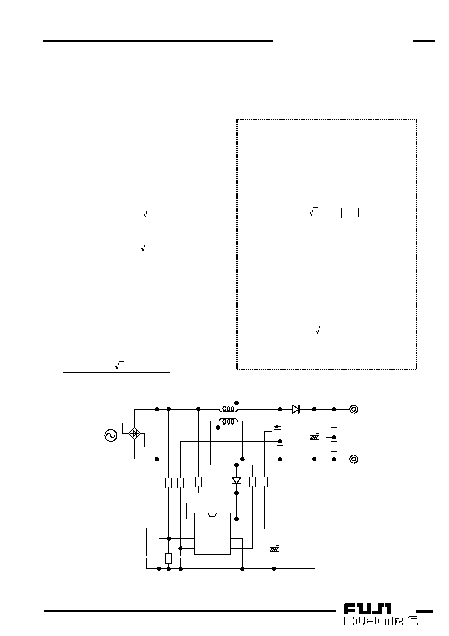
(1)Designing a PFC converter
The following description is a sample of designing of
a PFC converter with FA5500A/FA5501A using a circuit
shown in Fig. 13. However, this is just a sample of
calculating. If you want to use the components or
circuits calculated in this process, be sure to test and
determine in actual circuit. In addition, be sure to
consider and check the characteristics, the tolerance
and the rating of each component including this IC.
(1-1)
Specification of PFC converter
To begin designing, the following specification of PFC
converter is determined.
Input voltage range (Vrms):
Vac(min.) to Vac(max.)
Output voltage (V):
Vo (> 2 ×Vac (max.) )
Maximum Output power(W):
Po
Output voltage (Vo) should be set higher than the
peak value of input voltage (= 2 ×Vac (max.)) because
the PFC converter is a boost type topology.
(1-2)
Designing inductance of L1
The switching frequencies are determined with
input-output conditions and the value of inductor
because PFC converter operates in critical conduction
mode (see Supplement). Therefore, the value of
inductor L1 (Lp) can be determined with input-output
conditions and the minimum operating frequency.
When efficiency of PFC is
η and the minimum
operating frequency is fsw (min.), Lp is calculated by
following equation.
Lp=
Vo
Po
fsw
2
)
Vac
2
(Vo
Vac
.)
(min
.)
(min
2
.)
(min
×
η
×
×
It
is
recommended
to
set
fsw(min)
between
20kHz-100kHz.
Assume
that
the
efficiency
η is
approximately 90% in calculating.
Supplement:
Inductance and switching frequencies
On and off period of each switching cycle can be
calculated with the following equation.
η
×
=
2
Vac
Po
Lp
2
Ton
ω
×
η
×
=
1
t
n
si
Vac
2
Vo
Vac
Po
Lp
2
Toff
2
where,
ω=2×π×fac
fac: AC line frequency (Hz)
In theory, according to the equation above, if
input-output conditions are constant, Ton is also
constant.
On
the
other
hand,
Toff
changes
corresponding to each instantaneous voltage of AC line,
maximum at
ωt =90°, minimum at ωt =0°.
Then,
switching frequencies can be calculated with the
following
equation
according
to
the
relationships
described above:
(
)
Vo
Po
Lp
2
t
n
si
Vac
2
Vo
Vac
fsw
2
×
η
×
ω
×
×
=
The
switching
frequencies
always
change
corresponding to each instantaneous voltage of AC line.
Vac
C1
L1 Np
Ns
R3
R6
R7
D2
R5
R8
FA5500A/01A
FB
COMP OUT
VCC
MUL
GND
IS
ZCD
C4
R4
C6
C3
C5
Rs
Q1
D1
C2
R1
R2
Po
Vo
Fig.13
Typical application circuit
相关PDF资料 |
PDF描述 |
|---|---|
| FA5500AN | 1 A SWITCHING CONTROLLER, PDSO8 |
| FA5500AP | 1 A SWITCHING CONTROLLER, PDIP8 |
| FA5516N | 1 A SWITCHING CONTROLLER, 143 kHz SWITCHING FREQ-MAX, PDSO8 |
| FA5517N | 1 A SWITCHING CONTROLLER, 110 kHz SWITCHING FREQ-MAX, PDSO8 |
| FA5516P | 1 A SWITCHING CONTROLLER, 143 kHz SWITCHING FREQ-MAX, PDIP8 |
相关代理商/技术参数 |
参数描述 |
|---|---|
| FA5501AP/AN | 制造商:未知厂家 制造商全称:未知厂家 功能描述: |
| FA5502 | 制造商:未知厂家 制造商全称:未知厂家 功能描述:FA5502P/M is a control IC for a power factor correction system. |
| FA5502M-H1 | 制造商:Fuji Electric 功能描述: |
| FA5502M-TE1 | 制造商:Fuji Electric 功能描述:1.5 A POWER FACTOR CONTROLLER, 150 kHz SWITCHING FREQ-MAX, 16 Pin Plastic SOP 制造商:Fuji Semiconductors, Inc. 功能描述:1.5 A POWER FACTOR CONTROLLER, 150 kHz SWITCHING FREQ-MAX, 16 Pin Plastic SOP |
| FA5502P/M | 制造商:未知厂家 制造商全称:未知厂家 功能描述:FA5502P/M is a control IC for a power factor correction system. |
发布紧急采购,3分钟左右您将得到回复。