- 您现在的位置:买卖IC网 > PDF目录67412 > FA5501AP (FUJI ELECTRIC CO LTD) 1 A SWITCHING CONTROLLER, PDIP8 PDF资料下载
参数资料
| 型号: | FA5501AP |
| 厂商: | FUJI ELECTRIC CO LTD |
| 元件分类: | 稳压器 |
| 英文描述: | 1 A SWITCHING CONTROLLER, PDIP8 |
| 封装: | DIP-8 |
| 文件页数: | 13/26页 |
| 文件大小: | 228K |
| 代理商: | FA5501AP |
FA5500AP/AN, FA5501AP/AN
20
Quality is our message
(1-3)
Designing auxiliary winding of L1
The auxiliary winding typically has two functions:
-Detecting that inductor current reaches zero
-Supplying Vcc voltage of IC
To achieve these functions, you have to determine a
proper ratio of it to the main winding.
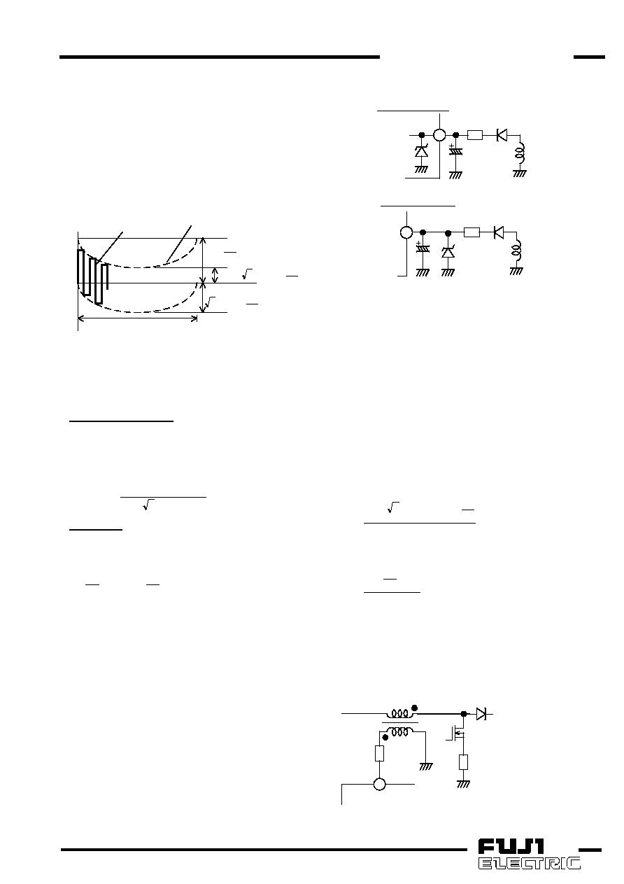
The voltage of auxiliary winding always changes
according to each instantaneous voltage of AC line. The
outline of the auxiliary winding voltage is shown in Fig.
14.
auxilliary winding
voltage
Np
Ns
)
Vac
2
Vo
(
×
Np
Ns
Vo
×
Np
Ns
Vac
2
×
1/2 of line frequency
0
envelope
Fig.14
Auxiliary winding voltage
The following conditions should be satisfied based on
this various voltage.
ZCD Threshold Voltage
The
threshold
voltage
of
ZCD
comparator
is
1.87V(max.)
when
ZCD
pin
voltage
rises.
It
is
necessary for the minimum voltage of auxiliary winding
to
exceed this
threshold voltage. Therefore,
the
following condition must be satisfied.
()
.
max
Vac
2
Vo
1.87
Np
/
Ns
×
>
Vcc voltage
The following condition must be satisfied, so that Vcc
voltage will be set between 12V and 28V according to
the recommended condition.
Vo
28
Ns/Np
Vo
12
<
The turns ratio Ns/Np must satisfy both two condition.
If the boost voltage ratio of PFC (the ratio of Vo to
Vac) is too small, the turns ratio can not satisfy both
condition. This problem can be solved with following
methods.
-Attach two auxiliary windings for both ZCD and Vcc
respectively.
-Set ZCD condition preceding Vcc condition. In this
case, there is possibility for Vcc to exceed the
recommended conditions. Therefore, clamp the Vcc
with internal ZD or additional ZD (Fig. 15). In this
case, a resistance for current limit (R11) is needed
between the auxiliary winding and Vcc pin. In
addition, especially when using internal ZD, mind
that “Total power supply and zener current” and
“Power dissipation” must not exceed the absolute
maximum rating value.
D2
R11
C5
sub
VCC
8
internal
ZD
using internal ZD
D2
R11
C5
sub
VCC
8
external
ZD
using external ZD
Fig.15
Vcc clamp circuit
(1-4)
ZCD pin circuit
The auxiliary winding voltage is monitored by ZCD
pin in order to detect that the inductor current reaches
zero. A resistor for current limit (R5) is connected
between ZCD pin and the auxiliary winding because of
rating current of ZCD pin. The most appropriate value of
R5 is determined by evaluating in the actual circuit.
However, a current out of or into the ZCD pin
should be within 3mA as shown in the recommended
operating conditions so that the IC will operate
normally. Therefore, the following conditions should
be satisfied.
For lower clamp
3
10
3
Np
Ns
.)
Vac(max
2
0
.
1
5
R
×
+
>
For upper clamp
3
10
3
0
.
7
Np
Ns
Vo
5
R
×
×
>
On the other hand, if the current out of or into the
ZCD pin is too small, unstable operation may occur.
Therefore, current limiting resistor of R5 should be
below 47k
.
<
k
47
5
R
5
ZCD
R5
L1
D1
Q1
Rs
Fig.16
ZCD pin circuit
相关PDF资料 |
PDF描述 |
|---|---|
| FA5500AN | 1 A SWITCHING CONTROLLER, PDSO8 |
| FA5500AP | 1 A SWITCHING CONTROLLER, PDIP8 |
| FA5516N | 1 A SWITCHING CONTROLLER, 143 kHz SWITCHING FREQ-MAX, PDSO8 |
| FA5517N | 1 A SWITCHING CONTROLLER, 110 kHz SWITCHING FREQ-MAX, PDSO8 |
| FA5516P | 1 A SWITCHING CONTROLLER, 143 kHz SWITCHING FREQ-MAX, PDIP8 |
相关代理商/技术参数 |
参数描述 |
|---|---|
| FA5501AP/AN | 制造商:未知厂家 制造商全称:未知厂家 功能描述: |
| FA5502 | 制造商:未知厂家 制造商全称:未知厂家 功能描述:FA5502P/M is a control IC for a power factor correction system. |
| FA5502M-H1 | 制造商:Fuji Electric 功能描述: |
| FA5502M-TE1 | 制造商:Fuji Electric 功能描述:1.5 A POWER FACTOR CONTROLLER, 150 kHz SWITCHING FREQ-MAX, 16 Pin Plastic SOP 制造商:Fuji Semiconductors, Inc. 功能描述:1.5 A POWER FACTOR CONTROLLER, 150 kHz SWITCHING FREQ-MAX, 16 Pin Plastic SOP |
| FA5502P/M | 制造商:未知厂家 制造商全称:未知厂家 功能描述:FA5502P/M is a control IC for a power factor correction system. |
发布紧急采购,3分钟左右您将得到回复。