- 您现在的位置:买卖IC网 > PDF目录67412 > FA5501AP (FUJI ELECTRIC CO LTD) 1 A SWITCHING CONTROLLER, PDIP8 PDF资料下载
参数资料
| 型号: | FA5501AP |
| 厂商: | FUJI ELECTRIC CO LTD |
| 元件分类: | 稳压器 |
| 英文描述: | 1 A SWITCHING CONTROLLER, PDIP8 |
| 封装: | DIP-8 |
| 文件页数: | 16/26页 |
| 文件大小: | 228K |
| 代理商: | FA5501AP |

FA5500AP/AN, FA5501AP/AN
23
Quality is our message
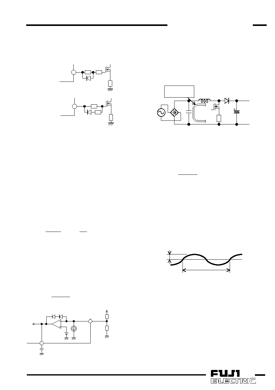
If the effect of RC filter is not enough, connect OUT
pin and MOSFET as shown in Fig. 25 in order to reduce
driving current to turn the MOSFET on. In this circuit,
drive currents to turn the MOSFET on and off can be
set independently.
OUT
7
R8
R9
Rs
or
OUT
7
R8
R9 Rs
Fig.25
Gate drive circuit
The inductor current reaches zero just before the
MOSFET turns on and MOSFET current rises from
around zero when MOSFET is on. Therefore, even if
the driving current to turn on is set small and the
switching speed becomes a little slow, the loss of
MOSFET does not increase extremely.
(1-8)
Input/output of error amplifier
PFC output voltage Vo is divided down and input to
FB pin. Vo is controlled so that the FB pin voltage is
equal to the internal reference. This IC has a current
source (IFB) of 2.5A(typ.) connected FB pin internally.
Therefore, the relationship between Vo and the voltage
divider resistor can be expressed with the following
equation.
amplifier
error
of
ce
tan
c
Transcondu
:
Gm
,
where
I
1
R
Gm
I
Vref
2
R
2
R
1
R
Vo
FB
×
+
+
×
+
=
PFC
output
voltage
contains
ripple
voltage
associated with twice the line frequency. If this ripple
voltage appears at the output of error amplifier, PFC
does not operate stably. To avoid this, a capacitor
should be inserted between COMP pin and GND so
that the bandwidth is set to about 20Hz. The bandwidth
can be expressed with the following equation.
3
C
2
Gm
BW
×
π
×
=
1
2
MUL
ERRAMP
Vref
=2.5V(typ)
=2.5A
IFB
COMP
C3
FB
R1
R2
Vo
(typ)
Fig.26
Input/output of error amplifier circuit
(1-9)
Input/output capacitor
The input capacitor C1 rejects the switching ripples of
inductor current and prevents it from flowing to AC line.
Therefore, the larger C1 is, the smaller the switching
ripples contained in AC input current are. But larger C1
may causes of lowering power factor.
In calculation, capacity of C1 is assumed as 1F per
1A of maximum AC input current. The most appropriate
capacity should be determined by evaluating power
factor and AC line noises in the actual circuit.
switching
ripple current
L1
Q1
Rs
C1
D1
C2
Fig.27
Input capacitor circuit
PFC output contains ripple voltage of twice the line
frequency. The output capacitor C2 suppresses this
ripple voltage.
The ripple voltage appearing on the output voltage
can be expressed by the following equation.
2
C
2
o
I
V
p)
ripple(0
×
ω
×
≈
where,
fac
2
×
π
×
=
ω
fac: AC line frequency [Hz]
If the output voltage including ripple voltage reaches
up to the overvoltage threshold, the IC cannot operate
properly. Therefore, C2 should be selected satisfying
the following equation.
Vripple(0-p)<0.075×Vo
2×fac
Vripple(0-p)
Vo
Fig.28
Output ripple voltage
相关PDF资料 |
PDF描述 |
|---|---|
| FA5500AN | 1 A SWITCHING CONTROLLER, PDSO8 |
| FA5500AP | 1 A SWITCHING CONTROLLER, PDIP8 |
| FA5516N | 1 A SWITCHING CONTROLLER, 143 kHz SWITCHING FREQ-MAX, PDSO8 |
| FA5517N | 1 A SWITCHING CONTROLLER, 110 kHz SWITCHING FREQ-MAX, PDSO8 |
| FA5516P | 1 A SWITCHING CONTROLLER, 143 kHz SWITCHING FREQ-MAX, PDIP8 |
相关代理商/技术参数 |
参数描述 |
|---|---|
| FA5501AP/AN | 制造商:未知厂家 制造商全称:未知厂家 功能描述: |
| FA5502 | 制造商:未知厂家 制造商全称:未知厂家 功能描述:FA5502P/M is a control IC for a power factor correction system. |
| FA5502M-H1 | 制造商:Fuji Electric 功能描述: |
| FA5502M-TE1 | 制造商:Fuji Electric 功能描述:1.5 A POWER FACTOR CONTROLLER, 150 kHz SWITCHING FREQ-MAX, 16 Pin Plastic SOP 制造商:Fuji Semiconductors, Inc. 功能描述:1.5 A POWER FACTOR CONTROLLER, 150 kHz SWITCHING FREQ-MAX, 16 Pin Plastic SOP |
| FA5502P/M | 制造商:未知厂家 制造商全称:未知厂家 功能描述:FA5502P/M is a control IC for a power factor correction system. |
发布紧急采购,3分钟左右您将得到回复。