- 您现在的位置:买卖IC网 > PDF目录67412 > FA7703V (FUJI ELECTRIC CO LTD) 0.4 A DUAL SWITCHING CONTROLLER, 1000 kHz SWITCHING FREQ-MAX, PDSO16 PDF资料下载
参数资料
| 型号: | FA7703V |
| 厂商: | FUJI ELECTRIC CO LTD |
| 元件分类: | 稳压器 |
| 英文描述: | 0.4 A DUAL SWITCHING CONTROLLER, 1000 kHz SWITCHING FREQ-MAX, PDSO16 |
| 封装: | 1.10 MM, TSSOP-16 |
| 文件页数: | 5/21页 |
| 文件大小: | 242K |
| 代理商: | FA7703V |
13
Quality is our message
FA7703/04
8. Description of each circuit
(1)Reference Voltage Circuit
The reference voltage circuit of FA7703/04
generates the reference voltage (VREF) of
1.00V±1% compensated in temperature from
VCC voltage, and the regulated voltage (VREG)
of 2.2V ±2% for internal controlling. These
voltages start to output when the undervoltage
lockout protection (UVLO) is cancelled, and
they stabilize after the supply voltage (VCC)
reaches up to approx. 2.4V or higher. The
reference voltage (VREF) is connected to the
non-inverting input of Error Amplifier 1 and
serves as the reference voltage of Error
Amplifier 1. Because of Error Amplifiers have
offset voltage then, the precision of voltage in
practical use is 1.00V±2%. The voltage (VREF)
outputs externally from REF terminal, therefore,
it can serve as a stabilized power source. When
using it, be sure to set the output current 1mA
or below.
The regulated voltage (VREG) for internal
controlling serves as the stabilized power
source for maximum output duty setting or the
like. Be sure to set the output current 2mA or
below in operation in this case. This voltage
also serves as the control power source of all
the internal circuits of FA7703/04. A capacitor
for stabilization (CREG) is needed to be
connected
to
the
VREG
terminal.
See
recommended
operating
conditions
to
determine capacitance.
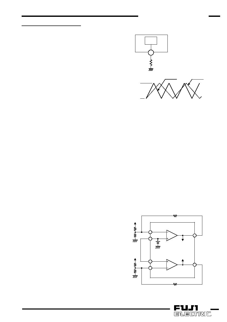
(2)Oscillator
The
oscillator
of
FA7703/04
generates
triangular
waveforms
by
charging
and
discharging the built-in capacitor. Any desired
oscillation frequency can be obtained by setting
the value of the resistor connected to RT
terminal (Fig. 1).
The voltage oscillates between approximately
0.65V and 1.10V in charging and discharging
with almost the same gradients (Fig. 2). Your
desired oscillation frequency can be determined
by changing the gradient using the resistor (RT)
connected to RT terminal. (Large RT: Low
frequency, small RT: High frequency) The
waveforms of oscillator cannot be observed from
the outside because a terminal for this purpose
is not provided.
Approximately DC 1V is output to RT terminal.
The oscillator output is connected to PWM
comparator.
(3)Error Amplifier Circuit
Error Amplifier 1 of FA7703/04 has the inverting
input IN1(-) terminal (Pin13). The non-Inverting
input is internally connected to the reference
voltage (VB) of 1.00V±2% at 25°C. Because
error Amplifier 2 of FA7703/04 has the inverting
input IN2(-) terminal (Pin5) and non-inverted
input IN2(+) terminal (Pin4) outputting externally,
various circuit can be designed by kinds of
external circuit structures. FB terminals (Pin6,
Pin12) are the outputs of Error Amplifiers.
Voltage Gain and phase compensation can be
set by connecting a capacitor (C) and a resistor
(R) between FB terminal and IN(-) terminal.(Fig.
3) For more information about the connection for
each output voltage of power supply, refer to
Design Advice.
Fig.2
RT value: large
RT value: small
0.65V
1.10V
Fig.3
12
13
4
5
6
14
Com p
VB
(1.0V)
Er.Am p.1
Er.Am p.2
IN1-
REF
FB1
FB2
IN2-
IN2+
Vout1
Vout2
RNF1
RNF2
R1
R2
R3
R4
1
OSC
RT
RT
Fig.1
相关PDF资料 |
PDF描述 |
|---|---|
| FA7704M | 0.4 A DUAL SWITCHING CONTROLLER, 1000 kHz SWITCHING FREQ-MAX, PDSO16 |
| FA7703M | 0.4 A DUAL SWITCHING CONTROLLER, 1000 kHz SWITCHING FREQ-MAX, PDSO16 |
| FA7738N | 5.5 A SWITCHING REGULATOR, 400 kHz SWITCHING FREQ-MAX, PDSO8 |
| FA7738P | 5.5 A SWITCHING REGULATOR, 400 kHz SWITCHING FREQ-MAX, PDIP8 |
| FAB2200UCX | 1.2 W, 2 CHANNEL, AUDIO AMPLIFIER, PBGA25 |
相关代理商/技术参数 |
参数描述 |
|---|---|
| FA7704 | 制造商:FUJI 制造商全称:Fuji Electric 功能描述:FUJI Power Supply Control IC |
| FA771 | 制造商:Black Box Corporation 功能描述:DB25 TO RJ45,8 WIRE,F MOD THUMBSCREW ADPTR KIT |
| FA7711V | 制造商:FUJI 制造商全称:Fuji Electric 功能描述:FUJI Power Supply Control IC |
| FA7726 | 制造商:FUJI 制造商全称:Fuji Electric 功能描述:45V Input Buck Converter 3ch/2ch IC with Power MOSFET |
| FA7730 | 制造商:FUJI 制造商全称:Fuji Electric 功能描述:45V Input Buck Converter 3ch/2ch IC with Power MOSFET |
发布紧急采购,3分钟左右您将得到回复。