- 您现在的位置:买卖IC网 > PDF目录67412 > FAN5061M (FAIRCHILD SEMICONDUCTOR CORP) SWITCHING CONTROLLER, 345 kHz SWITCHING FREQ-MAX, PDSO20 PDF资料下载
参数资料
| 型号: | FAN5061M |
| 厂商: | FAIRCHILD SEMICONDUCTOR CORP |
| 元件分类: | 稳压器 |
| 英文描述: | SWITCHING CONTROLLER, 345 kHz SWITCHING FREQ-MAX, PDSO20 |
| 封装: | SOIC-20 |
| 文件页数: | 6/18页 |
| 文件大小: | 149K |
| 代理商: | FAN5061M |
FAN5061
14
Pr
eliminar
y
Specication
with IDetect ≈ 50A, ISC is the desired current limit, and
RDS,on the high-side MOSFET’s on resistance. Remember to
make the RS large enough to include the effects of initial tol-
erance and temperature variation on the MOSFET’s RDS,on.
Alternately, use of a sense resistor in series with the source
of the MOSFET eliminates this source of inaccuracy in the
current limit.
As an example, Figure 4 shows the typical characteristic of
the DC-DC converter circuit with an FDB6030L high-side
MOSFET (RDS = 20m maximum at 25°C * 1.25 at 75°C =
25m
) and a 8.2K R
S.
Figure 4. FAN5061 Short Circuit Characteristic
The converter exhibits a normal load regulation characteristic
until the voltage across the MOSFET exceeds the internal
short circuit threshold of 50A * 8.2K
= 410mV, which
occurs at 410mV/25m
= 16.4A. (Note that this current limit
level can be as high as 410mV/15m
= 27A, if the MOSFET
has typical RDS,on rather than maximum, and is at 25°C).
If the current exceeds this limit for more than 30sec, the
FAN5061 shuts down all of its outputs, including its linear
regulators. They remain shut down until power is recycled.
Similarly, if any of the linear regulator outputs are loaded
heavily enough that their output voltage drops below 80% of
nominal, all FAN5061 outputs, including the switcher, are
shut off and remain off until power is recycled.
Schottky Diode Selection
The application circuit of Figure 1 shows a Schottky diode,
D1, which is used as a free-wheeling diode to assure that the
body-diode in Q2 does not conduct when the upper MOSFET
is turning off and the lower MOSFET is turning on. It is
undesirable for this diode to conduct because its high forward
voltage drop and long reverse recovery time degrades efciency,
and so the Schottky provides a shunt path for the current.
Since this time duration is very short, the selection criterion
for the diode is that the forward voltage of the Schottky at
the output current should be less than the forward voltage of
the MOSFET’s body diode.
Output Filter Capacitors
The output bulk capacitors of a converter help determine its
output ripple voltage and its transient response. It has already
been seen in the section on selecting an inductor that the ESR
helps set the minimum inductance, and the capacitance value
helps set the maximum inductance. For most converters,
however, the number of capacitors required is determined by
the transient response and the output ripple voltage, and these
are determined by the ESR and not the capacitance value.
That is, in order to achieve the necessary ESR to meet the
transient and ripple requirements, the capacitance value
required is already very large.
The most commonly used choice for output bulk capacitors is
aluminum electrolytics, because of their low cost and low ESR.
The only type of aluminum capacitor used should be those that
have an ESR rated at 100kHz. Consult Application Bulletin
AB-14 for detailed information on output capacitor selection.
The output capacitance should also include a number of
small value ceramic capacitors placed as close as possible to
the processor; 0.1F and 0.01F are recommended values.
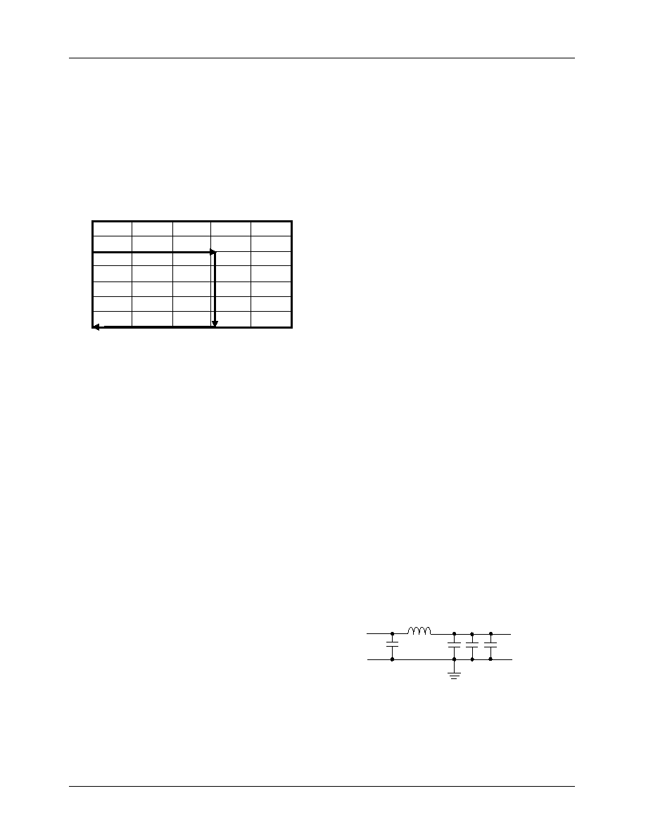
Input Filter
The DC-DC converter design may include an input inductor
between the system +5V supply and the converter input as
shown in Figure 5. This inductor serves to isolate the +5V
supply from the noise in the switching portion of the DC-DC
converter, and to limit the inrush current into the input capac-
itors during power up. A value of 2.5H is recommended.
It is necessary to have some low ESR aluminum electrolytic
capacitors at the input to the converter. These capacitors
deliver current when the high side MOSFET switches on.
Figure 5 shows 3 x 1000F, but the exact number required
will vary with the speed and type of the processor. For the
top speed Katmai and Coppermine, the capacitors should be
rated to take 9A and 6A of ripple current respectively.
Capacitor ripple current rating is a function of temperature,
and so the manufacturer should be contacted to nd out the
ripple current rating at the expected operational temperature.
For details on the design of an input lter, refer to Applica-
tions Bulletin AB-15.
Figure 8. Input Filter
V
OUT
(V)
Output Current (A)
0
5
10
15
20
25
2.5
H
5V
0.1
F
1000
F, 10V
Electrolytic
Vin
相关PDF资料 |
PDF描述 |
|---|---|
| FAN5201MSA | 6 A BATTERY CHARGE CONTROLLER, 275 kHz SWITCHING FREQ-MAX, PDSO24 |
| FAN5361UMP10X | SWITCHING REGULATOR, DSO6 |
| FAN5361UC13X | SWITCHING REGULATOR, PBGA6 |
| FAN5361UC15X | SWITCHING REGULATOR, PBGA6 |
| FAN5361UMP12X | SWITCHING REGULATOR, DSO6 |
相关代理商/技术参数 |
参数描述 |
|---|---|
| FAN5063 | 制造商:FAIRCHILD 制造商全称:Fairchild Semiconductor 功能描述:ACPI Dual Switch Controller |
| FAN5063A WAF | 制造商:Fairchild Semiconductor Corporation 功能描述: |
| FAN5063M | 功能描述:开关变换器、稳压器与控制器 aCPI Dual Switch Controller RoHS:否 制造商:Texas Instruments 输出电压:1.2 V to 10 V 输出电流:300 mA 输出功率: 输入电压:3 V to 17 V 开关频率:1 MHz 工作温度范围: 安装风格:SMD/SMT 封装 / 箱体:WSON-8 封装:Reel |
| FAN5063MX | 功能描述:开关变换器、稳压器与控制器 aCPI Dual Switch Controller RoHS:否 制造商:Texas Instruments 输出电压:1.2 V to 10 V 输出电流:300 mA 输出功率: 输入电压:3 V to 17 V 开关频率:1 MHz 工作温度范围: 安装风格:SMD/SMT 封装 / 箱体:WSON-8 封装:Reel |
| FAN5063-ZCA3026B WAF | 制造商:Fairchild Semiconductor Corporation 功能描述: |
发布紧急采购,3分钟左右您将得到回复。