- 您现在的位置:买卖IC网 > PDF目录67478 > FK1501-7RD0TB2 (POWER-ONE INC) 1-OUTPUT 150 W DC-DC REG PWR SUPPLY MODULE PDF资料下载
参数资料
| 型号: | FK1501-7RD0TB2 |
| 厂商: | POWER-ONE INC |
| 元件分类: | 电源模块 |
| 英文描述: | 1-OUTPUT 150 W DC-DC REG PWR SUPPLY MODULE |
| 封装: | METAL, CASE K02, MODULE |
| 文件页数: | 6/31页 |
| 文件大小: | 1251K |
| 代理商: | FK1501-7RD0TB2 |
第1页第2页第3页第4页第5页当前第6页第7页第8页第9页第10页第11页第12页第13页第14页第15页第16页第17页第18页第19页第20页第21页第22页第23页第24页第25页第26页第27页第28页第29页第30页第31页
K Series
DC-DC Converters >100 Watt
Rugged Environment
Edition 4/4.99
14/31
MELCHER
The Power Partners.
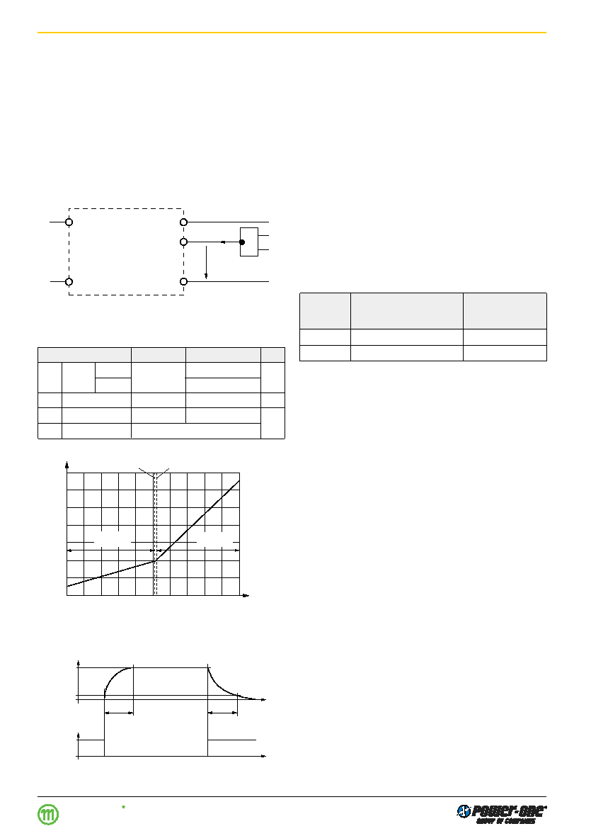
Fig. 15
Typical output response as a function of inhibit control
Table 5: Inhibit characteristics
Characteristic
Conditions
min
typ
max Unit
Uinh Inhibit
Uo = on
Ui min…Ui max
–50
0.8
V
voltage
Uo = off
2.4
50
Iinh
Inhibit current
Uinh = 0
–400
A
tr
Rise time
30
ms
tf
Fall time
depending on
Io
0
t
0
Inhibit
1
0.1
1
Uo/Uo nom
tr
tf
06001
Sense Lines
(Only for single output units 5.1 V, 12 V, 15 V, 24 V)
This feature enables for compensation of voltage drops
across the connector contacts and if necessary, across the
load lines. If the sense lines are connected at the load
rather than directly at the connector, the user should ensure
that
Uo max (between Vo1+ and Vo1–) is not exceeded. We
recommend connecting the sense lines directly at the fe-
male connector.
For further information, please refer to:
Application Notes.
To ensure correct operation, both sense lines (S+ and S–)
should be connected to their respective power outputs
(Vo1+ and Vo1–) and the voltage difference between any
sense line and its respective power output pin (as meas-
ured on the connector) should not exceed the following val-
ues:
Table 6: Maximum voltage compensation allowed using
sense lines
Output
Total voltage difference
Voltage difference
voltage
between sense lines and
between
their respective outputs
Vo– and S–
5.1 V
< 0.5 V
< 0.25 V
12 V, 15 V
< 1.0 V
< 0.25 V
If the output voltages are increased above
Uo nom via R-in-
put control, option P setting, remote sensing or option T, the
output currents must be reduced accordingly so that
Po nom is not exceeded.
Note: The output terminals Vo1+ and Vo1– must always be
connected to the load before connecting the sense lines S+
and S–, otherwise the unit will be damaged.
Auxiliary Functions
i Inhibit for Remote On and Off
Note: With open i input: Output is disabled (
Uo = off).
The outputs of the module may be enabled or disabled by
means of a logic signal (TTL, CMOS, etc.) applied between
the inhibit input i and the negative pin of output 1 (Vo1–). In
systems with several units, this feature can be used, for ex-
ample, to control the activation sequence of the converters.
If the inhibit function is not required, connect the inhibit pin
18 to pin 14 to enable the outputs (active low logic, fail
safe). For output response refer to:
Hold-up Time and Out-
put Response.
Vi+
Vi–
Vo–
i
Vo+
Iinh
Uinh
06031
1.6
0.8
0
–0.8
–50
Uinh [V]
Iinh [mA]
–30
0
–10
10
30
50
2.0
1.2
0.4
–0.4
Uinh = 0.8 V
Uo = on
Uo = off
Uinh = 2.4 V
06032
Fig. 13
Definition of Uinh and Iinh.
Fig. 14
Typical inhibit current Iinh versus inhibit voltage Uinh
相关PDF资料 |
PDF描述 |
|---|---|
| FK1501-9PD0B2 | 1-OUTPUT 150 W DC-DC REG PWR SUPPLY MODULE |
| FK1501-9PD8TB2 | 1-OUTPUT 150 W DC-DC REG PWR SUPPLY MODULE |
| FK1501-9RDDT | 1-OUTPUT 150 W DC-DC REG PWR SUPPLY MODULE |
| FK1601-9PD8B2 | 1-OUTPUT 150 W DC-DC REG PWR SUPPLY MODULE |
| FK1601-9RD8TB2 | 1-OUTPUT 150 W DC-DC REG PWR SUPPLY MODULE |
相关代理商/技术参数 |
参数描述 |
|---|---|
| FK1501-9ER | 制造商:Power-One 功能描述:DCDC - Bulk |
| F-K15-1 | 制造商:Cosel Usa Inc 功能描述:Optional Accessories, OP Series |
| F-K15-2 | 制造商:Cosel Usa Inc 功能描述:Optional Accessories, OP Series |
| FK15M | 功能描述:TAPERED END PENETRATION PROBE RoHS:是 类别:测试设备 >> 测试引线 - 热电偶,温度探头 系列:FK 标准包装:1 系列:6543 类型:J 型热电偶 使用:液体,半固体 尖端 - 类型:防浸渍 / 穿透式,圆头 插头类型:超微型(热电偶插头) 探针温度范围:-40 ~ 2000°F(-40 ~ 1093°C) 线缆长度:- 线缆绝缘:- 插头颜色:黑 探针长度:12.000"(304.80mm) 探针材料:- |
| FK15S BLK | 制造商:SCHUTZINGER 功能描述:4MM PLG STACK BLACK |
发布紧急采购,3分钟左右您将得到回复。