- 您现在的位置:买卖IC网 > PDF目录68995 > FSR510R09GZ (FAIRCHILD SEMICONDUCTOR CORP) SWITCHING CONTROLLER, ZFM6 PDF资料下载
参数资料
| 型号: | FSR510R09GZ |
| 厂商: | FAIRCHILD SEMICONDUCTOR CORP |
| 元件分类: | 稳压器 |
| 英文描述: | SWITCHING CONTROLLER, ZFM6 |
| 封装: | ROHS COMPLIANT, TO-220, 6 PIN |
| 文件页数: | 10/12页 |
| 文件大小: | 0K |
| 代理商: | FSR510R09GZ |
2009 Fairchild Semiconductor Corporation
www.fairchildsemi.com
FSR510 Rev. 1.0.4
7
FSR510
—
Highly
Integrated
Synchronous
Rectificati
on
Combination
Controller
Functional Description
Basic Operation Principle of QR flyback
converter with FSR510
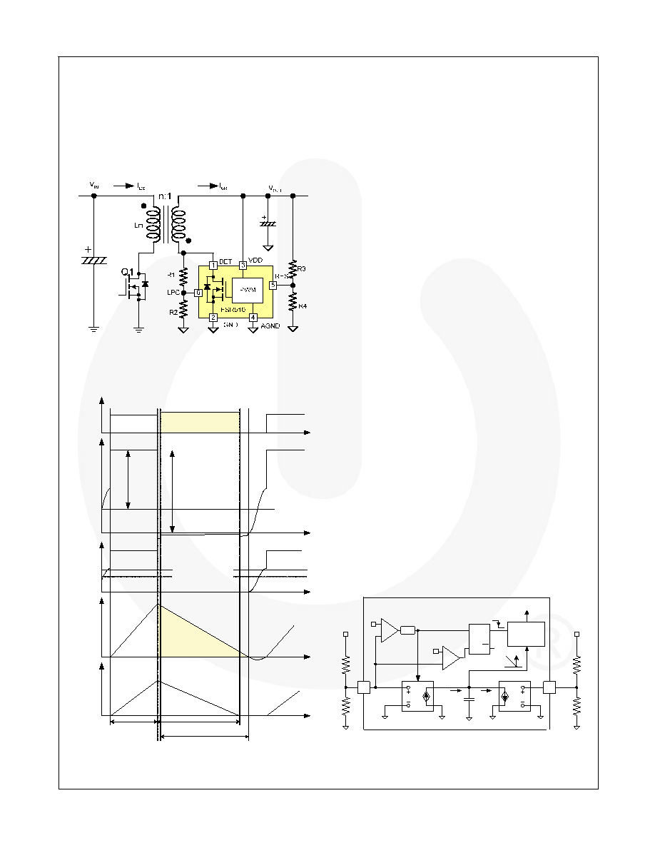
Figure 5 shows the simplified circuit diagram of flyback
converter using FSFR510. Typical waveforms are
shown in Figure 6.
Figure 5. Typical Application Circuit
V
OUT
V
DET
I
M
V
IN/n
Primary
MOSFET
V
GS
Synchronous Rectifier
MOSFET
Primary
MOSFET
V
CT
V
LPC
0.075 V
OUT+0.1
t
PM.ON
I
DS
I
SR /n
V
IN/n+VOUT
t
L.DIS
t
CT.DIS
0.05 V
OUT+0.1
Figure 6. Typical Waveforms
The
basic
operations
of quasi-resonant flyback
converter with SR are:
During the primary-side MOSFET ON time (tPM.ON),
input voltage (VIN) is applied across the primary-side
inductor (Lm). Then MOSFET current (IDS) increases
linearly from zero to the peak value. During this time,
the DET pin voltage is the sum of output voltage
(VOUT) and the reflected input voltage (VIN/n).
When the primary-side MOSFET is turned off, the
energy stored in the inductor forces the body diode
of SR MOSFET to be turned on. Then the DET
voltage drops to almost zero and the SR controller
turns on SR MOSFET. During this period, the current
through SR linearly decreases to zero. By linear
predict control, the SR MOSFET is turned off just
before the SR current reaches zero and the current
continues flowing through the body diode of SR
MOSFET until it reaches zero.
When the SR MOSFET body diode current reaches
zero, SR MOSFET body diode is naturally reverse
biased and DET voltage begins to oscillate by the
resonance between the primary-side inductor (Lm)
and effective capacitance loaded across MOSFET
with an amplitude of output voltage, as shown in the
second waveform of Figure 6. The QR flyback
converter turns on the primary-side MOSFET when
DET voltage reaches its peak by resonance.
Linear Predict Timing Control
The SR MOSFET is turned on when the SR MOSFET
body diode starts conducting and DET voltage drops to
zero. FSR510 uses LPC pin with a voltage divider to
sense the DET voltage and the threshold voltage for
LPC to trigger SR MOSFET is 0.05VOUT+0.1, as shown
in the third waveform of Figure 6.
The SR MOSFET is turned off just before the SR
current reaches zero by linear predict timing control. To
guarantee the proper operation SR, it is important to
turn off SR MOSFET just before SR current reaches
zero so that the body diode of SR MOSFET is naturally
turned off. Figure 7 shows the internal block for linear
predict timing control.
5A/V
V
CT
0.075 V
OUT
+
-
6
LPC
5
Enable
1A/V
S
R
Q
+
-
C
T
i
CHR
i
DISCHR
RES
PWM
Block
V
OUT
DET
R1
R2
R4
R3
0.05 V
OUT
Tu rn -ON
Tu rn -OFF
SR MOSFET
Gate Drive
BL K
1s
Figure 7. Linear Predict Block
相关PDF资料 |
PDF描述 |
|---|---|
| FT1034BMH-1.2B-FT | 2-OUTPUT TWO TERM VOLTAGE REFERENCE, 1.225 V, MBCY3 |
| FTF1100MF1 | SPECIALTY ANALOG CIRCUIT, XMA |
| FW100H9 | 1-OUTPUT 100 W DC-DC REG PWR SUPPLY MODULE |
| FW050H9 | 1-OUTPUT 50 W DC-DC REG PWR SUPPLY MODULE |
| FW150H | 1-OUTPUT 150 W DC-DC REG PWR SUPPLY MODULE |
相关代理商/技术参数 |
参数描述 |
|---|---|
| FSR73K2BTR10J | 制造商:KOA Speer Electronics Inc 功能描述:RESISTOR, CURRENT SENSE, 0.25 W, 1, 2, 5 %, 100, 200, 500, 800 ppm, 0.03 ohm - 10 ohm, SURFACE MOUNT, 1206 |
| FSRB041020RNB00B | 功能描述:EMI/RFI 抑制器及铁氧体 267ohm @100MHz Ring Core RoHS:否 制造商:Fair-Rite 产品:Ferrite Cores 阻抗:365 Ohms 容差: 最大直流电流: 最大直流电阻: 工作温度范围:- 55 C to + 125 C 封装 / 箱体: 端接类型:SMD/SMT |
| FSRB060040RNB00B | 功能描述:EMI/RFI 抑制器及铁氧体 290ohm @100MHz Ring Core RoHS:否 制造商:Fair-Rite 产品:Ferrite Cores 阻抗:365 Ohms 容差: 最大直流电流: 最大直流电阻: 工作温度范围:- 55 C to + 125 C 封装 / 箱体: 端接类型:SMD/SMT |
| FSRB071040RNB00B | 功能描述:EMI/RFI 抑制器及铁氧体 222ohm @100MHz Ring Core RoHS:否 制造商:Fair-Rite 产品:Ferrite Cores 阻抗:365 Ohms 容差: 最大直流电流: 最大直流电阻: 工作温度范围:- 55 C to + 125 C 封装 / 箱体: 端接类型:SMD/SMT |
| FSRB090060RNB00B | 功能描述:EMI/RFI 抑制器及铁氧体 356ohm @100MHz Ring Core RoHS:否 制造商:Fair-Rite 产品:Ferrite Cores 阻抗:365 Ohms 容差: 最大直流电流: 最大直流电阻: 工作温度范围:- 55 C to + 125 C 封装 / 箱体: 端接类型:SMD/SMT |
发布紧急采购,3分钟左右您将得到回复。