- 您现在的位置:买卖IC网 > PDF目录68995 > FSR510R09GZ (FAIRCHILD SEMICONDUCTOR CORP) SWITCHING CONTROLLER, ZFM6 PDF资料下载
参数资料
| 型号: | FSR510R09GZ |
| 厂商: | FAIRCHILD SEMICONDUCTOR CORP |
| 元件分类: | 稳压器 |
| 英文描述: | SWITCHING CONTROLLER, ZFM6 |
| 封装: | ROHS COMPLIANT, TO-220, 6 PIN |
| 文件页数: | 11/12页 |
| 文件大小: | 0K |
| 代理商: | FSR510R09GZ |
2009 Fairchild Semiconductor Corporation
www.fairchildsemi.com
FSR510 Rev. 1.0.4
8
FSR510
—
Highly
Integrated
Synchronous
Rectificati
on
Combination
Controller
The linear predict timing control circuit generates a
replica (VCT) of magnetizing current of flyback
transformer using internal timing capacitor (CT), as
shown in Figure 7. Using the internal capacitor voltage,
the inductor discharge time (tL.DIS) can be detected
indirectly, as shown in the last waveform of Figure 6.
When CT is discharged to zero, the SR controller turns
off the SR MOSFET.
The voltage-second balance equation for the primary
side inductance of flyback converter is given as
..
IN
PM ON
OUT
L DIS
Vt
n V
t
=
(1)
Then, the inductor current discharge time is given as:
.
IN
PM ON
LDIS
OUT
Vt
t
nV
=
(2)
When the voltage scale-down ratio between RES and
LPC is defined as K as below:
(
)
()
2
1
2
4
3
4
/
R
K
+
=
(3)
The current-second balance equation for internal timing
capacitor (CT) is obtained as:
..
5
((
)
IN
OUT
PM ON
OUT
CT DIS
V
VV
t
V
t
Kn
+
=
(4)
Then, the discharge time of CT is given as:
.
5
((
)
IN
OUT
PM ON
CT DIS
OUT
V
VV
t
Kn
t
V
+
=
(5)
When the voltage scale-down ratio between RES and
LPC (K) is 5, the discharge time of CT (tCT.DIS) is same
as inductor current discharge time (tL.DIS). However,
considering the tolerance of voltage divider resistors
and internal circuit, the scale-down ratio (K) should be
larger than 5 to guarantee that tCT.DIS is shorter than
tL.DIS. It is typical to set K around 5.5~6.
Since the voltage-to-current conversion circuit for the
LPC pin is enabled only when LPC voltage goes above
0.075VOUT+0.1, as shown in the third waveform of
Figure 7, the voltage divider for LPC should be
determined so that it can satisfy:
.
2
12
()
0.075
0.1
IN MIN
OUT
V
R
VV
RR
n
+
>
+
(6)
where VIN.MIN is the minimum input voltage of the flyback
converter.
When designing the voltage divider networks for LPC
and RES, the linear operation range of LPC and RES
(1~4V) should be also considered as:
.
2
12
()
4
IN MAX
OUT
V
R
V
RR
n
+
<
+
(7)
4
3
4
<
+
OUT
V
R
(8)
DCM Operation
FSR510
can
be
also
used
for
Discontinuous
Conduction Mode (DCM) or extended quasi-resonant
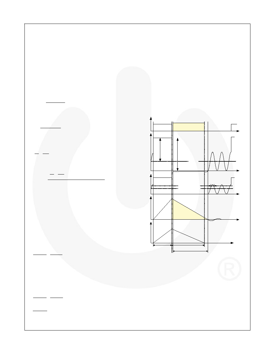
operation (valley switching). In DCM operation, the DET
voltage continues resonating until the primary-side
MOSFET is turned on, as depicted in Figure 8. While
DET voltage is resonating, DET voltage and LPC
voltage drop to zero by resonance, which can trigger
the turn-on of the SR MOSFET. To prevent fault
triggering of the SR MOSFET in DCM operation,
blanking time is introduced for LPC voltage. The SR
MOSFET is not turned on even when LPC voltage
drops below 0.05VOUT+0.1 unless LPC voltage stays
above 0.075VOUT +0.1 longer than the blanking time
(1
μs). The turn-on of the SR MOFET is inhibited for
2.5
μs once the SR MOSFET is turned off to prevent
fault triggering.
V
OUT
V
DET
IM
V
IN/n
Primary
MOSFET
V
GS
Synchronous Rectifier
MOSFET
V
CT
V
LPC
0.075 V
OUT+0.1
t
PM.ON
IDS
ISR /n
V
IN/n+VOUT
t L.DIS
t
CT.DIS
Blanking time
0.05 VOUT+0.1
Figure 8. DCM Operation of FSR510
Green-Mode Operation
To minimize the power consumption at light-load
condition, the SR circuit is disabled when the load
decreases. As illustrated in Figure 9, the discharge
times of inductor and internal timing capacitor decrease
as load decreases. When the discharge time of internal
timing capacitor is shorter than tGREEN-ON (around 4.8s)
for more than nine cycles, the SR circuit enters green
mode, as shown in Figure 9. Once FSR510 enters
green mode, the SR MOSFET stops switching and the
major internal block is shut down to further reduce
operating current of the SR controller. In green mode,
the operating current reduces to 800A. This allows
相关PDF资料 |
PDF描述 |
|---|---|
| FT1034BMH-1.2B-FT | 2-OUTPUT TWO TERM VOLTAGE REFERENCE, 1.225 V, MBCY3 |
| FTF1100MF1 | SPECIALTY ANALOG CIRCUIT, XMA |
| FW100H9 | 1-OUTPUT 100 W DC-DC REG PWR SUPPLY MODULE |
| FW050H9 | 1-OUTPUT 50 W DC-DC REG PWR SUPPLY MODULE |
| FW150H | 1-OUTPUT 150 W DC-DC REG PWR SUPPLY MODULE |
相关代理商/技术参数 |
参数描述 |
|---|---|
| FSR73K2BTR10J | 制造商:KOA Speer Electronics Inc 功能描述:RESISTOR, CURRENT SENSE, 0.25 W, 1, 2, 5 %, 100, 200, 500, 800 ppm, 0.03 ohm - 10 ohm, SURFACE MOUNT, 1206 |
| FSRB041020RNB00B | 功能描述:EMI/RFI 抑制器及铁氧体 267ohm @100MHz Ring Core RoHS:否 制造商:Fair-Rite 产品:Ferrite Cores 阻抗:365 Ohms 容差: 最大直流电流: 最大直流电阻: 工作温度范围:- 55 C to + 125 C 封装 / 箱体: 端接类型:SMD/SMT |
| FSRB060040RNB00B | 功能描述:EMI/RFI 抑制器及铁氧体 290ohm @100MHz Ring Core RoHS:否 制造商:Fair-Rite 产品:Ferrite Cores 阻抗:365 Ohms 容差: 最大直流电流: 最大直流电阻: 工作温度范围:- 55 C to + 125 C 封装 / 箱体: 端接类型:SMD/SMT |
| FSRB071040RNB00B | 功能描述:EMI/RFI 抑制器及铁氧体 222ohm @100MHz Ring Core RoHS:否 制造商:Fair-Rite 产品:Ferrite Cores 阻抗:365 Ohms 容差: 最大直流电流: 最大直流电阻: 工作温度范围:- 55 C to + 125 C 封装 / 箱体: 端接类型:SMD/SMT |
| FSRB090060RNB00B | 功能描述:EMI/RFI 抑制器及铁氧体 356ohm @100MHz Ring Core RoHS:否 制造商:Fair-Rite 产品:Ferrite Cores 阻抗:365 Ohms 容差: 最大直流电流: 最大直流电阻: 工作温度范围:- 55 C to + 125 C 封装 / 箱体: 端接类型:SMD/SMT |
发布紧急采购,3分钟左右您将得到回复。