- 您现在的位置:买卖IC网 > PDF目录68996 > FTF1100MF1 (INFINEON TECHNOLOGIES AG) SPECIALTY ANALOG CIRCUIT, XMA PDF资料下载
参数资料
| 型号: | FTF1100MF1 |
| 厂商: | INFINEON TECHNOLOGIES AG |
| 元件分类: | 模拟信号调理 |
| 英文描述: | SPECIALTY ANALOG CIRCUIT, XMA |
| 文件页数: | 7/39页 |
| 文件大小: | 400K |
| 代理商: | FTF1100MF1 |
第1页第2页第3页第4页第5页第6页当前第7页第8页第9页第10页第11页第12页第13页第14页第15页第16页第17页第18页第19页第20页第21页第22页第23页第24页第25页第26页第27页第28页第29页第30页第31页第32页第33页第34页第35页第36页第37页第38页第39页
FingerTIP
Infineon Technologies
15/38
FTF 1100 MF1 V2.0 databook 3.3 (05.00)
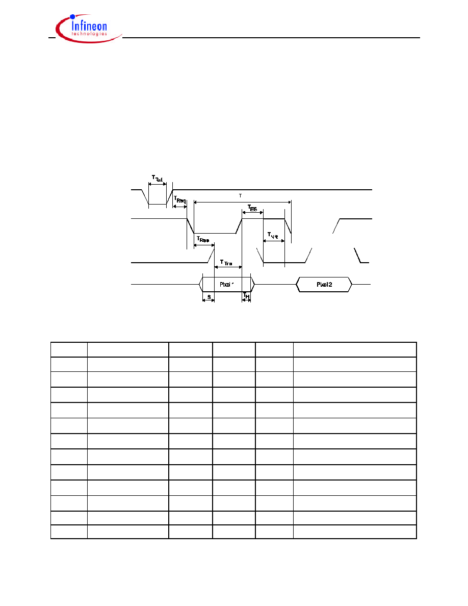
3.4 Timing of the EPP 1.9 Protocol Used by the FingerTIP
Figure 6 shows the EPP protocol for a data read cycle and the timing. Table 4 shows the
values of the timing parameters. The pad characteristics are described in chapter 5.
After a reset, which sets the pixel pointer to position (1,1), readout of the first byte can be
started. A readout cycle is started when the /REQUEST line switches to low. The sensor
outputs the data byte and switches the READY line to high if the data is valid. In the next
step the PC reads the data byte and afterwards sets the /REQUEST line to high. Now the
sensor switches the READY line to low and the data lines change to tristate. Now a new
readout cycle can be started. During readout of the image no reset is needed.
tristate
Cyc
DA0 – DA7
from sensor
READY
from sensor
/REQUEST
from PC
/RESET
from PC
Figure 6: EPP Timing Diagram of the FingerTIP. I/O Level: TTL Compatible
Interval Name
Min.
Typ.
Max.
Dependency [PC or Sensor]
Power-on reset
80
s
TRst
Reset impulse
2
s
Reset [PC]
TReq
Reset to request
300
s
[PC]
TS
Data setup time
10 ns
50 ns
100 ns
Data setup time [Sensor]
TH
Data hold time
100 ns
Data hold time [Sensor]
TRea
Request to ready
600 ns
700 ns
Response time valid data [Sensor]
TTra
Transfer time
200 ns
Transfer data to PC [PC]
TES
Deadlock time
50 ns
125 ns
[Sensor]
TNR
Next read
30 ns
[Sensor]
TCyc
Transfer of 1 Byte
≤ 1.0 s
[PC / Sensor]
tRO / tFO
Output Rise/Fall Time
0.20 V/ns
0.50 V/ns
0.80 V/ns @ CI/O_Line = 50 pF
tRI / tFI
Input Rise/Fall Time
0.05 V/ns
0.50 V/ns
0.80 V/ns @ CI/O_Line = 50 pF
Table 4: Timing Parameters; Typical Values for 1MHz EPP Clock Frequency (V CC = 5V)
相关PDF资料 |
PDF描述 |
|---|---|
| FW100H9 | 1-OUTPUT 100 W DC-DC REG PWR SUPPLY MODULE |
| FW050H9 | 1-OUTPUT 50 W DC-DC REG PWR SUPPLY MODULE |
| FW150H | 1-OUTPUT 150 W DC-DC REG PWR SUPPLY MODULE |
| FW050H | 1-OUTPUT 50 W DC-DC REG PWR SUPPLY MODULE |
| FW100H | 1-OUTPUT 100 W DC-DC REG PWR SUPPLY MODULE |
相关代理商/技术参数 |
参数描述 |
|---|---|
| FTF1100MF1V2.0 | 制造商:Rochester Electronics LLC 功能描述:- Bulk |
| FTF1100MF1V2.1 | 制造商:Rochester Electronics LLC 功能描述:- Bulk |
| FTF3020-C | 制造商:PHILIPS 制造商全称:NXP Semiconductors 功能描述:Full Frame CCD Image Sensor |
| FTF3020-C/EG | 制造商:PHILIPS 制造商全称:NXP Semiconductors 功能描述:Full Frame CCD Image Sensor |
| FTF3020-C/HG | 制造商:PHILIPS 制造商全称:NXP Semiconductors 功能描述:Full Frame CCD Image Sensor |
发布紧急采购,3分钟左右您将得到回复。