- 您现在的位置:买卖IC网 > PDF目录11610 > GRM2165C1HR50CD01J (Murata Electronics North America)CAP CER 0.5PF 50V NP0 0805 PDF资料下载
参数资料
| 型号: | GRM2165C1HR50CD01J |
| 厂商: | Murata Electronics North America |
| 文件页数: | 168/182页 |
| 文件大小: | 0K |
| 描述: | CAP CER 0.5PF 50V NP0 0805 |
| 标准包装: | 10,000 |
| 系列: | GRM |
| 电容: | 0.50pF |
| 电压 - 额定: | 50V |
| 容差: | ±0.25pF |
| 温度系数: | C0G,NP0 |
| 安装类型: | 表面贴装,MLCC |
| 工作温度: | -55°C ~ 125°C |
| 应用: | 通用 |
| 封装/外壳: | 0805(2012 公制) |
| 尺寸/尺寸: | 0.079" L x 0.049" W(2.00mm x 1.25mm) |
| 厚度(最大): | 0.028"(0.70mm) |
| 包装: | 带卷 (TR) |
第1页第2页第3页第4页第5页第6页第7页第8页第9页第10页第11页第12页第13页第14页第15页第16页第17页第18页第19页第20页第21页第22页第23页第24页第25页第26页第27页第28页第29页第30页第31页第32页第33页第34页第35页第36页第37页第38页第39页第40页第41页第42页第43页第44页第45页第46页第47页第48页第49页第50页第51页第52页第53页第54页第55页第56页第57页第58页第59页第60页第61页第62页第63页第64页第65页第66页第67页第68页第69页第70页第71页第72页第73页第74页第75页第76页第77页第78页第79页第80页第81页第82页第83页第84页第85页第86页第87页第88页第89页第90页第91页第92页第93页第94页第95页第96页第97页第98页第99页第100页第101页第102页第103页第104页第105页第106页第107页第108页第109页第110页第111页第112页第113页第114页第115页第116页第117页第118页第119页第120页第121页第122页第123页第124页第125页第126页第127页第128页第129页第130页第131页第132页第133页第134页第135页第136页第137页第138页第139页第140页第141页第142页第143页第144页第145页第146页第147页第148页第149页第150页第151页第152页第153页第154页第155页第156页第157页第158页第159页第160页第161页第162页第163页第164页第165页第166页第167页当前第168页第169页第170页第171页第172页第173页第174页第175页第176页第177页第178页第179页第180页第181页第182页
�� �
�
�!� Note� ?� Please� read� rating� and� !� CAUTION� (for� storage,� operating,� rating,� soldering,� mounting� and� handling)� in� this� catalog� to� prevent� smoking� and/or� burning,� etc.�
�?� This� catalog� has� only� typical� speci?cations.� Therefore,� please� approve� our� product� speci?cations� or� transact� the� approval� sheet� for� product� speci?cations� before� ordering.�
�C02E.pdf�
�Sep.25,2013�
�!� Caution�
�Continued� from� the� preceding� page.�
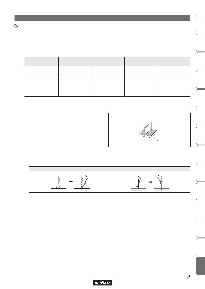
�2.� Check� the� cropping� method� for� the� printed� circuit� board�
�in� advance.�
�2-1.� Printed� circuit� board� cropping� shall� be� carried� out� by�
�using� a� jig� or� an� apparatus� (Disk� separator,� router�
�type� separator,� etc.)� to� prevent� the� mechanical� stress�
�that� can� occur� to� the� board.�
�Board� Separation� Method�
�Hand� Separation�
�Nipper� Separation�
�(1)� Board� Separation� Jig�
�Board� Separation� Apparatus�
�(2)� Disk� Separator� (3)� Router� Type� Separator�
�Level� of� stress� on� board�
�Recommended�
�High�
��
�Medium�
�*�
�Medium�
�*�
�Low�
�?�
�·� Board� handling�
�Hand� and� nipper�
�·� Board� handling�
�·� Layout� of� slits�
�Notes�
�separation� apply� a� high�
�level� of� stress.�
�Use� another� method.�
�·� Board� bending� direction�
�·� Layout� of� capacitors�
�·� Design� of� V� groove�
�·� Arrangement� of� blades�
�Board� handling�
�·� Controlling� blade� life�
�*� When� a� board� separation� jig� or� disk� separator� is� used,� if� the� following� precautions� are� not� observed,� a� large� board� deflection� stress� will� occur� and� the� capacitors�
�may� crack.� Use� router� type� separator� if� at� all� possible.�
�(1)� Example� of� a� suitable� jig�
�[In� the� case� of� Single-side� Mounting]�
�An� outline� of� the� board� separation� jig� is� shown� as�
�[Outline� of� Jig]�
�follows.� Recommended� example:� Stress� on� the�
�component� mounting� position� can� be� minimized� by�
�holding� the� portion� close� to� the� jig,� and� bend� in� the�
�direction� towards� the� side� where� the� capacitors� are�
�mounted.� Not� recommended� example:� The� risk� of�
�cracks� occurring� in� the� capacitors� increases� due� to�
�large� stress� being� applied� to� the� component�
�mounting� position,� if� the� portion� away� from� the� jig�
�is� held� and� bent� in� the� direction� opposite� the� side�
�where� the� capacitors� are� mounted.�
�Recommended�
�Printed� Circuit� Board�
�V-groove�
�Board� Cropping� Jig�
�Not� recommended�
�Printed� Circuit� Board�
�Direction� of� Load�
�Components�
�Load� Point�
�Direction� of� Load�
�Load� Point�
�Printed� Circuit� Board�
�Components�
�[In� the� case� of� Double-sided� Mounting]�
�Since� components� are� mounted� on� both� sides� of� the�
�board,� the� risk� of� cracks� occurring� can� not� be�
�avoided� with� the� above� method.�
�Therefore,� implement� the� following� measures� to�
�prevent� stress� from� being� applied� to� the� components.�
�(Measures)�
�(1)� Consider� introducing� a� router� type� separator.�
�If� it� is� difficult� to� introduce� a� router� type� separator,�
�implement� the� following� measures.� (Refer� to� item�
�1.� Mounting� Position)�
�(2)� Mount� the� components� at� a� right� angle� to� the�
�board� separation� surface.�
�(3)� When� mounting� components� near� the� board�
�separation� point,� add� slits� in� the� separation�
�position� near� the� component.�
�(4)� Keep� the� mounting� position� of� the� components�
�away� from� the� board� separation� point.�
�Continued� on� the� following� page.�
�149�
�相关PDF资料 |
PDF描述 |
|---|---|
| GRM2165C1HR50CD01D | CAP CER 0.5PF 50V NP0 0805 |
| VE-J3N-IW-F1 | CONVERTER MOD DC/DC 18.5V 100W |
| GRM2165C1H9R0DZ01D | CAP CER 9PF 50V NP0 0805 |
| GRM2165C1H8R0DZ01D | CAP CER 8PF 50V NP0 0805 |
| GRM2165C1H7R0DZ01D | CAP CER 7PF 50V NP0 0805 |
相关代理商/技术参数 |
参数描述 |
|---|---|
| GRM2165C1HR50CD01K | 功能描述:多层陶瓷电容器MLCC - SMD/SMT 0805 0.50pF 50volt C0G +/-0.25pF RoHS:否 制造商:American Technical Ceramics (ATC) 电容:10 pF 容差:1 % 电压额定值:250 V 温度系数/代码:C0G (NP0) 外壳代码 - in:0505 外壳代码 - mm:1414 工作温度范围:- 55 C to + 125 C 产品:Low ESR MLCCs 封装:Reel |
| GRM2165C1HR50CD01L | 功能描述:多层陶瓷电容器MLCC - SMD/SMT 0805 0.50pF 50volt C0G +/-0.25pF RoHS:否 制造商:American Technical Ceramics (ATC) 电容:10 pF 容差:1 % 电压额定值:250 V 温度系数/代码:C0G (NP0) 外壳代码 - in:0505 外壳代码 - mm:1414 工作温度范围:- 55 C to + 125 C 产品:Low ESR MLCCs 封装:Reel |
| GRM2165C1HR50CD31B | 功能描述:多层陶瓷电容器MLCC - SMD/SMT 0805 0.50pF 50volt C0G +/-0.25pF RoHS:否 制造商:American Technical Ceramics (ATC) 电容:10 pF 容差:1 % 电压额定值:250 V 温度系数/代码:C0G (NP0) 外壳代码 - in:0505 外壳代码 - mm:1414 工作温度范围:- 55 C to + 125 C 产品:Low ESR MLCCs 封装:Reel |
| GRM2165C1HR50CD31D | 功能描述:多层陶瓷电容器MLCC - SMD/SMT 0805 0.50pF 50volt C0G +/-0.25pF RoHS:否 制造商:American Technical Ceramics (ATC) 电容:10 pF 容差:1 % 电压额定值:250 V 温度系数/代码:C0G (NP0) 外壳代码 - in:0505 外壳代码 - mm:1414 工作温度范围:- 55 C to + 125 C 产品:Low ESR MLCCs 封装:Reel |
| GRM2165C1HR50CD31J | 功能描述:多层陶瓷电容器MLCC - SMD/SMT 0805 0.50pF 50volt C0G +/-0.25pF RoHS:否 制造商:American Technical Ceramics (ATC) 电容:10 pF 容差:1 % 电压额定值:250 V 温度系数/代码:C0G (NP0) 外壳代码 - in:0505 外壳代码 - mm:1414 工作温度范围:- 55 C to + 125 C 产品:Low ESR MLCCs 封装:Reel |
发布紧急采购,3分钟左右您将得到回复。