- 您现在的位置:买卖IC网 > PDF目录11610 > GRM2165C1HR50CD01J (Murata Electronics North America)CAP CER 0.5PF 50V NP0 0805 PDF资料下载
参数资料
| 型号: | GRM2165C1HR50CD01J |
| 厂商: | Murata Electronics North America |
| 文件页数: | 172/182页 |
| 文件大小: | 0K |
| 描述: | CAP CER 0.5PF 50V NP0 0805 |
| 标准包装: | 10,000 |
| 系列: | GRM |
| 电容: | 0.50pF |
| 电压 - 额定: | 50V |
| 容差: | ±0.25pF |
| 温度系数: | C0G,NP0 |
| 安装类型: | 表面贴装,MLCC |
| 工作温度: | -55°C ~ 125°C |
| 应用: | 通用 |
| 封装/外壳: | 0805(2012 公制) |
| 尺寸/尺寸: | 0.079" L x 0.049" W(2.00mm x 1.25mm) |
| 厚度(最大): | 0.028"(0.70mm) |
| 包装: | 带卷 (TR) |
第1页第2页第3页第4页第5页第6页第7页第8页第9页第10页第11页第12页第13页第14页第15页第16页第17页第18页第19页第20页第21页第22页第23页第24页第25页第26页第27页第28页第29页第30页第31页第32页第33页第34页第35页第36页第37页第38页第39页第40页第41页第42页第43页第44页第45页第46页第47页第48页第49页第50页第51页第52页第53页第54页第55页第56页第57页第58页第59页第60页第61页第62页第63页第64页第65页第66页第67页第68页第69页第70页第71页第72页第73页第74页第75页第76页第77页第78页第79页第80页第81页第82页第83页第84页第85页第86页第87页第88页第89页第90页第91页第92页第93页第94页第95页第96页第97页第98页第99页第100页第101页第102页第103页第104页第105页第106页第107页第108页第109页第110页第111页第112页第113页第114页第115页第116页第117页第118页第119页第120页第121页第122页第123页第124页第125页第126页第127页第128页第129页第130页第131页第132页第133页第134页第135页第136页第137页第138页第139页第140页第141页第142页第143页第144页第145页第146页第147页第148页第149页第150页第151页第152页第153页第154页第155页第156页第157页第158页第159页第160页第161页第162页第163页第164页第165页第166页第167页第168页第169页第170页第171页当前第172页第173页第174页第175页第176页第177页第178页第179页第180页第181页第182页
�� �
�
�!� Note� ?� Please� read� rating� and� !� CAUTION� (for� storage,� operating,� rating,� soldering,� mounting� and� handling)� in� this� catalog� to� prevent� smoking� and/or� burning,� etc.�
�?� This� catalog� has� only� typical� speci?cations.� Therefore,� please� approve� our� product� speci?cations� or� transact� the� approval� sheet� for� product� speci?cations� before� ordering.�
�C02E.pdf�
�Sep.25,2013�
�Notice�
�c� Rating�
�1.� Operating� Temperature�
�1.� The� operating� temperature� limit� depends� on� the� capacitor.�
�1-1.� Do� not� apply� temperatures� exceeding� the� upper�
�operating� temperature.�
�It� is� necessary� to� select� a� capacitor� with� a� suitable�
�rated� temperature� that� will� cover� the� operating�
�temperature� range.�
�It� is� also� necessary� to� consider� the� temperature�
�distribution� in� equipment� and� the� seasonal�
�temperature� variable� factor.�
�1-2.� Consider� the� self-heating� factor� of� the� capacitor.�
�The� surface� temperature� of� the� capacitor� shall� be�
�the� upper� operating� temperature� or� less� when�
�including� the� self-heating� factors.�
�2.� Atmosphere� Surroundings� (gaseous� and� liquid)�
�1.� Restriction� on� the� operating� environment� of� capacitors.�
�1-1.� Capacitors,� when� used� in� the� above,� unsuitable,�
�c� Soldering� and� Mounting�
�1.� PCB� Design�
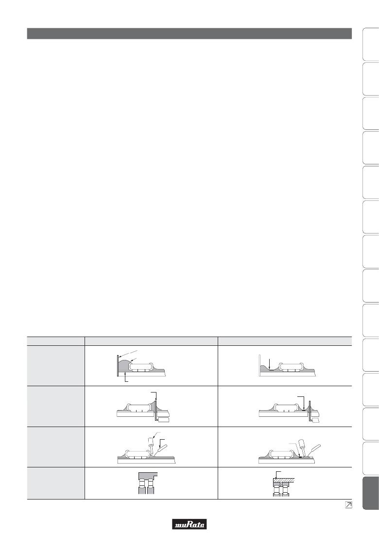
�1.� Notice� for� Pattern� Forms�
�1-1.� Unlike� leaded� components,� chip� components� are�
�susceptible� to� flexing� stresses� since� they� are�
�mounted� directly� on� the� substrate.�
�They� are� also� more� sensitive� to� mechanical� and�
�thermal� stresses� than� leaded� components.�
�Excess� solder� fillet� height� can� multiply� these� stresses�
�and� cause� chip� cracking.� When� designing� substrates,�
�take� land� patterns� and� dimensions� into� consideration�
�to� eliminate� the� possibility� of� excess� solder� fillet�
�height.�
�Pattern� Forms�
�Prohibited�
�Chassis�
�Solder� (ground)�
�operating� environments� may� deteriorate� due� to�
�the� corrosion� of� the� terminations� and� the�
�penetration� of� moisture� into� the� capacitor.�
�1-2.� The� same� phenomenon� as� the� above� may� occur�
�when� the� electrodes� or� terminals� of� the� capacitor�
�are� subject� to� moisture� condensation.�
�1-3.� The� deterioration� of� characteristics� and� insulation�
�resistance� due� to� the� oxidization� or� corrosion� of�
�terminal� electrodes� may� result� in� breakdown� when�
�the� capacitor� is� exposed� to� corrosive� or� volatile�
�gases� or� solvents� for� long� periods� of� time.�
�3.� Piezo-electric� Phenomenon�
�1.� When� using� high� dielectric� constant� type� capacitors� in�
�AC� or� pulse� circuits,� the� capacitor� itself� vibrates� at�
�specific� frequencies� and� noise� may� be� generated.�
�Moreover,� when� the� mechanical� vibration� or� shock� is�
�added� to� the� capacitor,� noise� may� occur.�
�1-2.� There� is� a� possibility� of� chip� cracking� caused� by� PCB�
�expansion/contraction� with� heat,� because� stress� on� a�
�chip� is� different� depending� on� PCB� material� and�
�structure.� When� the� thermal� expansion� coefficient�
�greatly� differs� between� the� board� used� for� mounting�
�and� the� chip,� it� will� cause� cracking� of� the� chip� due� to�
�the� thermal� expansion� and� contraction.� When� small�
�size� capacitors� of� 1005� size� or� less� are� mounted� on� a�
�single-layered� glass� epoxy� board,� it� will� also� cause�
�cracking� of� the� chip� for� the� same� reason.�
�Correct�
�Solder� Resist�
�Placing� Close� to� Chassis�
�Electrode� Pattern�
�Lead� Wire�
�Solder� Resist�
�Placing�
�of� Chip� Components�
�and� Leaded� Components�
�Soldering� Iron�
�Placing�
�of� Leaded� Components�
�Lead� Wire�
�Solder� Resist�
�after� Chip� Component�
�Solder� Resist�
�Lateral� Mounting�
�Continued� on� the� following� page.�
�153�
�相关PDF资料 |
PDF描述 |
|---|---|
| GRM2165C1HR50CD01D | CAP CER 0.5PF 50V NP0 0805 |
| VE-J3N-IW-F1 | CONVERTER MOD DC/DC 18.5V 100W |
| GRM2165C1H9R0DZ01D | CAP CER 9PF 50V NP0 0805 |
| GRM2165C1H8R0DZ01D | CAP CER 8PF 50V NP0 0805 |
| GRM2165C1H7R0DZ01D | CAP CER 7PF 50V NP0 0805 |
相关代理商/技术参数 |
参数描述 |
|---|---|
| GRM2165C1HR50CD01K | 功能描述:多层陶瓷电容器MLCC - SMD/SMT 0805 0.50pF 50volt C0G +/-0.25pF RoHS:否 制造商:American Technical Ceramics (ATC) 电容:10 pF 容差:1 % 电压额定值:250 V 温度系数/代码:C0G (NP0) 外壳代码 - in:0505 外壳代码 - mm:1414 工作温度范围:- 55 C to + 125 C 产品:Low ESR MLCCs 封装:Reel |
| GRM2165C1HR50CD01L | 功能描述:多层陶瓷电容器MLCC - SMD/SMT 0805 0.50pF 50volt C0G +/-0.25pF RoHS:否 制造商:American Technical Ceramics (ATC) 电容:10 pF 容差:1 % 电压额定值:250 V 温度系数/代码:C0G (NP0) 外壳代码 - in:0505 外壳代码 - mm:1414 工作温度范围:- 55 C to + 125 C 产品:Low ESR MLCCs 封装:Reel |
| GRM2165C1HR50CD31B | 功能描述:多层陶瓷电容器MLCC - SMD/SMT 0805 0.50pF 50volt C0G +/-0.25pF RoHS:否 制造商:American Technical Ceramics (ATC) 电容:10 pF 容差:1 % 电压额定值:250 V 温度系数/代码:C0G (NP0) 外壳代码 - in:0505 外壳代码 - mm:1414 工作温度范围:- 55 C to + 125 C 产品:Low ESR MLCCs 封装:Reel |
| GRM2165C1HR50CD31D | 功能描述:多层陶瓷电容器MLCC - SMD/SMT 0805 0.50pF 50volt C0G +/-0.25pF RoHS:否 制造商:American Technical Ceramics (ATC) 电容:10 pF 容差:1 % 电压额定值:250 V 温度系数/代码:C0G (NP0) 外壳代码 - in:0505 外壳代码 - mm:1414 工作温度范围:- 55 C to + 125 C 产品:Low ESR MLCCs 封装:Reel |
| GRM2165C1HR50CD31J | 功能描述:多层陶瓷电容器MLCC - SMD/SMT 0805 0.50pF 50volt C0G +/-0.25pF RoHS:否 制造商:American Technical Ceramics (ATC) 电容:10 pF 容差:1 % 电压额定值:250 V 温度系数/代码:C0G (NP0) 外壳代码 - in:0505 外壳代码 - mm:1414 工作温度范围:- 55 C to + 125 C 产品:Low ESR MLCCs 封装:Reel |
发布紧急采购,3分钟左右您将得到回复。