- 您现在的位置:买卖IC网 > PDF目录385376 > HFA3861BIN (INTERSIL CORP) Direct Sequence Spread Spectrum Baseband Processor PDF资料下载
参数资料
| 型号: | HFA3861BIN |
| 厂商: | INTERSIL CORP |
| 元件分类: | 无绳电话/电话 |
| 英文描述: | Direct Sequence Spread Spectrum Baseband Processor |
| 中文描述: | TELECOM, CELLULAR, BASEBAND CIRCUIT, PQFP64 |
| 封装: | 10 X 10 MM, PLASTIC, MS-026ACD, TQFP-64 |
| 文件页数: | 14/36页 |
| 文件大小: | 733K |
| 代理商: | HFA3861BIN |
第1页第2页第3页第4页第5页第6页第7页第8页第9页第10页第11页第12页第13页当前第14页第15页第16页第17页第18页第19页第20页第21页第22页第23页第24页第25页第26页第27页第28页第29页第30页第31页第32页第33页第34页第35页第36页
14
The baseband processor uses time invariant correlation to strip
the PN spreading and phase processing to demodulate the
resulting signals in the header and DBPSK/DQPSK
demodulation modes. These operations are illustrated in Figure
13 which is an overall block diagram of the receiver processor.
In processing the DBPSK header, input samples from the I and
Q A/D converters are correlated to remove the spreading
sequence. The peak position of the correlation pulse is used to
determine the symbol timing. The sample stream is decimated
to the symbol rate and corrected for frequency offset prior to
PSK demodulation. Phase errors from the demodulator are fed
to the NCO through a lead/lag filter to maintain phase lock. The
carrier is de-rotated by the carrier tracking loop. The
demodulated data is differentially decoded and descrambled
before being sent to the header detection section.
In the 1Mbps DBPSK mode, data demodulation is performed
the same as in header processing. In the 2Mbps DQPSK
mode, the demodulator demodulates two bits per symbol
and differentially decodes these bit pairs. The bits are then
serialized and descrambled prior to being sent to the output.
In the CCK modes, the receiver removes carrier frequency
offsets and uses a bank of correlators to detect the
modulation. A biggest picker finds the largest correlation in
the I and Q Channels and determines the sign of those
correlations. For this to happen, the demodulator must know
the starting phase which is determined by referencing the
data to the last bit of the header. Each symbol demodulated
determines 1 or 2 nibbles of data. This is then serialized and
descrambled before being passed to the output.
Chip tracking in the CCK modes is chip decision directed.
Carrier tracking is via a lead/lag filter using a digital Costas
phase detector.
Acquisition Description
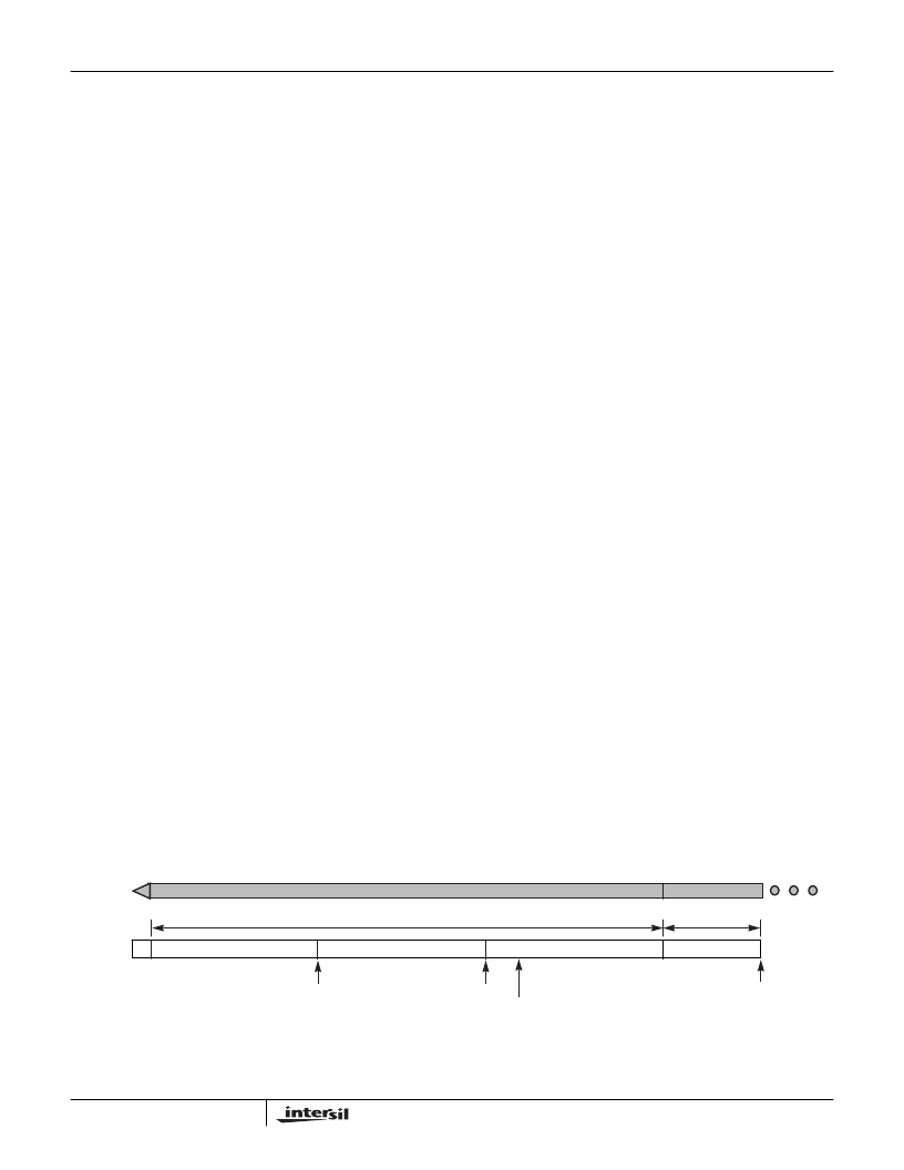
A projected worst case time line for the acquisition of a
signal with a short preamble and header is shown. The
synchronization part of the preamble is 56 symbols long
followed by a 16-bit SFD. The receiver must monitor the
antenna to determine if a signal is present. The timeline is
broken into 10
μ
s blocks (dwells) for the scanning process.
This length of time is necessary to allow enough integration
of the signal to make a good acquisition decision. This worst
case time line example assumes that the signal arrives part
way into the first dwell such as to just barely catch detection.
The signal and the scanning process are asynchronous and
the signal could start anywhere. In this timeline, it is
assumed that the signal is present in the first 10
μ
s dwell, but
was missed due to power amplifier ramp up.
Meanwhile signal quality and signal frequency
measurements are made simultaneous with symbol timing
measurements. A CS1 followed by SQ1 active, or two
consecutive SQ1’s will cause the part to finish the acquisition
phase and enter the tracking phase.
Prior to initial acquisition the NCO was inactive and DPSK
demodulation processing was used. Carrier phase
measurement are done on a symbol by symbol basis
afterward and coherent DPSK demodulation is in effect.
After a brief setup time as illustrated on the timeline of, the
signal begins to emerge from the demodulator.
It takes 7 more symbols to seed the descrambler before
valid data is available. This occurs in time for the SFD to be
received. At this time the demodulator is tracking and in the
coherent PSK demodulation mode it will no longer
acquire signals.
Channel Matched Filter (CMF) Description
The receive section shown in Figure 13 operates on the RAKE
receiver principle which maximizes the SNR of the signal by
combining the energy of multipath signal components. The
RAKE receiver is implemented with a Channel Matched Filter
(CMF) using a FIR filter structure with 16 taps. The CMF is
programmed by calculating the Channel Impulse Response
(CIR) of the channel and mathematically manipulating that to
form the tap coefficients of the CMF. Thus, the CMF is set to
compensate the channel characteristics that distort the signal.
Since the calculation of the CIR is inaccurate at low SNR or in
the presence of strong CW interference, the chip has
thresholds (CR 35, 49) that are set to substitute a default CMF
shape under those conditions. This default CMF shape is
designed to compensate only the known transmit and receive
non linearity.
2
20 SYMBOLS
56 SYMBOL SYNC
SFD
TX
POWER
RAMP
20 SYMBOLS
7 SYM
16 SYMBOLS
AGC SETTLE AND LOCK
AND INITIAL DETECTION
VERIFY AND CIR/FREQUENCY
ESTIMATION AND CMF/NCO
JAMMING
SFD DET
START DATA
SEED
DESCRAMBLER
START SFD DETECTION
FIGURE 10. ACQUISITION TIMELINE, NON DIVERSITY
HFA3861B
相关PDF资料 |
PDF描述 |
|---|---|
| HFA3861BIN96 | Direct Sequence Spread Spectrum Baseband Processor |
| HFA3925IA | null2.4GHz - 2.5GHz 250mW Power Amplifier |
| HFA3925IA96 | null2.4GHz - 2.5GHz 250mW Power Amplifier |
| HFA50PA60C | RxxP2xx Series - Econoline Unregulated DC-DC Converters; Input Voltage (Vdc): 05V; Output Voltage (Vdc): 15V; Power: 2W; EN 60950 certified, rated for 250VAC; UL-60950-1 / CSA C22.2 certified; 5.2kVDC Isolation for 1 Minute; Optional Continuous Short Circuit Protected; Wide Operating Temperature Range atfull 2 Watts Load, ?40??C to +85??C; Twin Chamber Transformer System; UL94V-0 Package Material; Efficiency to 80% |
| HFB50PA60C | Ultrafast, Soft Recovery Diode |
相关代理商/技术参数 |
参数描述 |
|---|---|
| HFA3861BIN96 | 制造商:INTERSIL 制造商全称:Intersil Corporation 功能描述:Direct Sequence Spread Spectrum Baseband Processor |
| HFA3861IV | 制造商:INTERSIL 制造商全称:Intersil Corporation 功能描述:Direct Sequence Spread Spectrum Baseband Processor |
| HFA3861IV96 | 制造商:INTERSIL 制造商全称:Intersil Corporation 功能描述:Direct Sequence Spread Spectrum Baseband Processor |
| HFA3863 | 制造商:INTERSIL 制造商全称:Intersil Corporation 功能描述:Direct Sequence Spread Spectrum Baseband Processor |
| HFA3863IN | 制造商:INTERSIL 制造商全称:Intersil Corporation 功能描述:Direct Sequence Spread Spectrum Baseband Processor |
发布紧急采购,3分钟左右您将得到回复。