- 您现在的位置:买卖IC网 > PDF目录385377 > HGTG24N60D1D (HARRIS SEMICONDUCTOR) 3.3V 36-mc CPLD PDF资料下载
参数资料
| 型号: | HGTG24N60D1D |
| 厂商: | HARRIS SEMICONDUCTOR |
| 元件分类: | 功率晶体管 |
| 英文描述: | 3.3V 36-mc CPLD |
| 中文描述: | 40 A, 600 V, N-CHANNEL IGBT, TO-247 |
| 文件页数: | 4/5页 |
| 文件大小: | 35K |
| 代理商: | HGTG24N60D1D |
3-110
HGTG24N60D1D
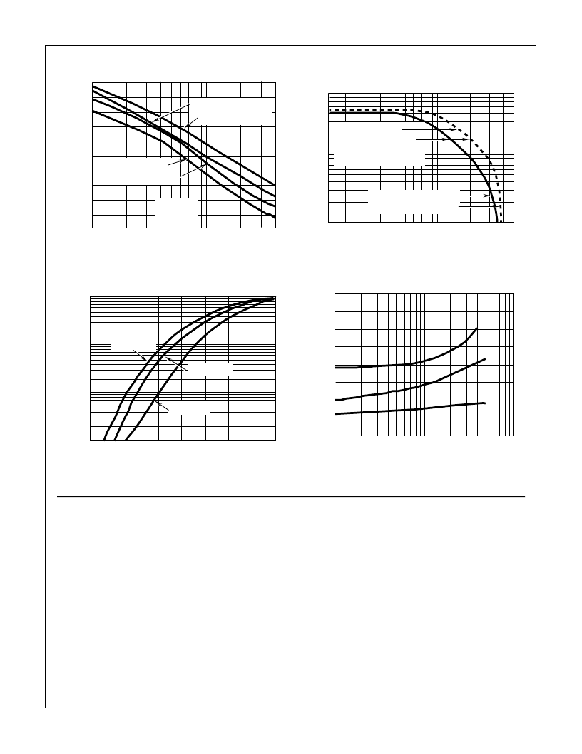
FIGURE 9. TURN-OFF DELAY vs COLLECTOR-EMITTER
CURRENT
FIGURE 10. OPERATING FREQUENCY vs COLLECTOR-
EMITTER CURRENT AND VOLTAGE
FIGURE 11. FORWARD VOLTAGE vs FORWARD CURRENT
CHARACTERISTIC
FIGURE 12. TYPICAL t
RR
, t
A
, t
B
vs FORWARD CURRENT
Typical Performance Curves
(Continued)
t
D
,
1
10
40
T
J
= +150
o
C
R
GE
= 25
L = 500
μ
H
I
CE
, COLLECTOR-EMITTER CURRENT (A)
V
CE
= 480V, V
GE
= 10V
1300
1200
1100
1000
900
800
700
600
500
400
300
V
CE
= 480V, V
GE
= 15V
V
CE
= 240V, V
GE
= 10V
V
CE
= 240V, V
GE
= 15V
80
10
1
f
O
,
1
10
50
I
CE
, COLLECTOR-EMITTER CURRENT (A)
T
J
= +150
o
C, T
C
= +100
o
C, R
GE
= 25
, L = 500
μ
H
V
CE
= 480V, V
GE
= 10V, 15V
V
CE
= 240V, V
GE
= 10V, 15V
f
MAX1
= 0.05/t
D(OFF)I
f
MAX2
= (P
D
- P
C
)/W
OFF
P
C
= DUTY FACTOR = 50%
R
θ
JC
= 1.0
o
C/W
P
D
= ALLOWABLE DISSIPATION
P
C
= CONDUCTION DISSIPATION
NOTE:
100
10
1.0
0.1
I
E
,
0.2
0.4
0.6
0.8
1.0
1.2
1.4
1.6
1.8
V
EC
, EMITTER-COLLECTOR VOLTAGE (V)
T
J
= +150
o
C
T
J
= +100
o
C
T
J
= +25
o
C
80
70
60
50
40
30
20
10
0
t
1
10
100
I
EC
, EMITTER-COLLECTOR CURRENT (A)
Operating Frequency Information
Operating frequency information for a typical device (Figure
10) is presented as a guide for estimating device performance
for a specific application. Other typical frequency vs collector
current (I
CE
) plots are possible using the information shown
for a typical unit in Figures 7, 8 and 9. The operating
frequency plot (Figure 10) of a typical device shows f
MAX1
or
f
MAX2
whichever is smaller at each point. The information is
based on measurements of a typical device and is bounded
by the maximum rated junction temperature.
f
MAX1
is defined by f
MAX1
= 0.05/t
D(OFF)I
. t
D(OFF)I
deadtime
(the denominator) has been arbitrarily held to 10% of the on-
state time for a 50% duty factor. Other definitions are possible.
t
D(OFF)I
is defined as the time between the 90% point of the
trailing edge of the input pulse and the point where the
collector current falls to 90% of its maximum value. Device
turn-off delay can establish an additional frequency limiting
condition for an application other than T
JMAX
. t
D(OFF)I
is
important when controlling output ripple under a lightly loaded
condition.
f
MAX2
is defined by f
MAX2
= (P
D
- P
C
)/W
OFF
. The allowable
dissipation (P
D
) is defined by P
D
= (T
JMAX
- T
C
)/R
θ
JC
. The sum
of device switching and conduction losses must not exceed P
D
.
A 50% duty factor was used (Figure 10) and the conduction
losses (P
C
) are approximated by P
C
= (V
CE
I
CE
)/2. W
OFF
is
defined as the integral of the instantaneous power loss starting
at the trailing edge of the input pulse and ending at the point
where the collector current equals zero (I
CE
= 0A).
The switching power loss (Figure 10) is defined as f
MAX2
W
OFF
. Turn-on switching losses are not included because they
can be greatly influenced by external circuit conditions and com-
ponents.
相关PDF资料 |
PDF描述 |
|---|---|
| HGTG24N60D1 | 36 MACROCELL 3.3 VOLT ISP CPLD |
| HGTG30N120D2 | 30A, 1200V N-Channel IGBT |
| HGTG30N60B3D | 60A, 600V, UFS Series N-Channel IGBT with Anti-Parallel Hyperfast Diode(60A, 600V, UFS系列 带超快二极管N沟道绝缘栅双极型晶体管) |
| HGTG30N60B3 | 60A, 600V, UFS Series N-Channel IGBT(60A, 600V, UFS系列 N沟道绝缘栅双极型晶体管) |
| HGTG30N60C3D | 63A, 600V, UFS Series N-Channel IGBT with Anti-Parallel Hyperfast Diodes |
相关代理商/技术参数 |
参数描述 |
|---|---|
| HGTG24N60DID | 制造商:Harris Corporation 功能描述: |
| HGTG27N120BN | 功能描述:IGBT 晶体管 72A 1200V NPT Series N-Ch IGBT RoHS:否 制造商:Fairchild Semiconductor 配置: 集电极—发射极最大电压 VCEO:650 V 集电极—射极饱和电压:2.3 V 栅极/发射极最大电压:20 V 在25 C的连续集电极电流:150 A 栅极—射极漏泄电流:400 nA 功率耗散:187 W 最大工作温度: 封装 / 箱体:TO-247 封装:Tube |
| HGTG27N120BN | 制造商:Fairchild Semiconductor Corporation 功能描述:IGBT IC |
| HGTG27N120BN_04 | 制造商:FAIRCHILD 制造商全称:Fairchild Semiconductor 功能描述:72A, 1200V, NPT Series N-Channel IGBT |
| HGTG27N60C3DR | 制造商:Rochester Electronics LLC 功能描述:- Bulk 制造商:Harris Corporation 功能描述: |
发布紧急采购,3分钟左右您将得到回复。