- 您现在的位置:买卖IC网 > PDF目录385377 > HGTG32N60E2 (HARRIS SEMICONDUCTOR) 72 MACROCELL 5 VOLT ISP CPLD - NOT RECOMMENDED for NEW DESIGN PDF资料下载
参数资料
| 型号: | HGTG32N60E2 |
| 厂商: | HARRIS SEMICONDUCTOR |
| 元件分类: | 功率晶体管 |
| 英文描述: | 72 MACROCELL 5 VOLT ISP CPLD - NOT RECOMMENDED for NEW DESIGN |
| 中文描述: | 50 A, 600 V, N-CHANNEL IGBT, TO-247 |
| 文件页数: | 4/4页 |
| 文件大小: | 33K |
| 代理商: | HGTG32N60E2 |
3-123
All Intersil semiconductor products are manufactured, assembled and tested under
ISO9000
quality systems certification.
Intersil products are sold by description only. Intersil Corporation reserves the right to make changes in circuit design and/or specifications at any time without
notice. Accordingly, the reader is cautioned to verify that data sheets are current before placing orders. Information furnished by Intersil is believed to be accurate
and reliable. However, no responsibility is assumed by Intersil or its subsidiaries for its use; nor for any infringements of patents or other rights of third parties which
may result from its use. No license is granted by implication or otherwise under any patent or patent rights of Intersil or its subsidiaries.
For information regarding Intersil Corporation and its products, see web site
http://www.intersil.com
Sales Office Headquarters
NORTH AMERICA
Intersil Corporation
P. O. Box 883, Mail Stop 53-204
Melbourne, FL 32902
TEL: (407) 724-7000
FAX: (407) 724-7240
TEL: (32) 2.724.2111
FAX: (32) 2.724.22.05
EUROPE
Intersil SA
Mercure Center
100, Rue de la Fusee
1130 Brussels, Belgium
ASIA
Intersil (Taiwan) Ltd.
Taiwan Limited
7F-6, No. 101 Fu Hsing North Road
Taipei, Taiwan
Republic of China
TEL: (886) 2 2716 9310
FAX: (886) 2 2715 3029
HGTG32N60E2
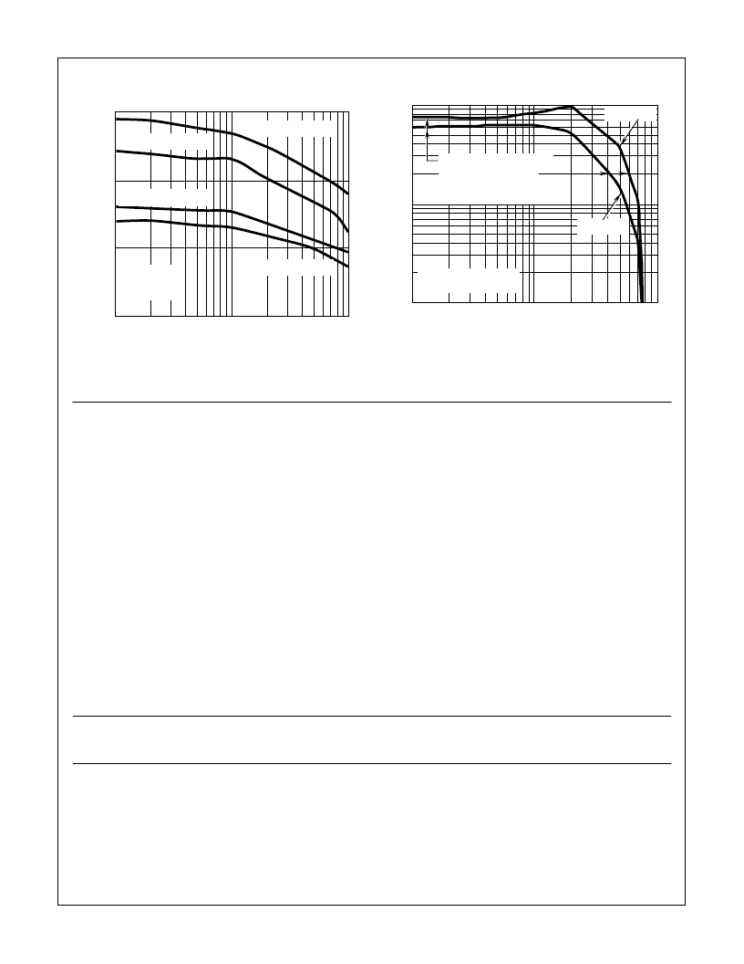
FIGURE 9. TURN-OFF DELAY vs COLLECTOR-EMITTER
CURRENT
FIGURE 10. OPERATING FREQUENCY vs COLLECTOR-
EMITTER CURRENT AND VOLTAGE
Typical Performance Curves
(Continued)
1.5
1.0
0.5
0.0
t
D
,
μ
s
1
10
100
T
J
= +150
o
C
V
CE
= 480V
L = 50
μ
H
I
CE
, COLLECTOR-EMITTER CURRENT (A)
V
GE
= 15V, R
G
= 50
V
GE
= 10V, R
G
= 50
V
GE
= 15V, R
G
= 25
V
GE
= 10V, R
G
= 25
100
10
1
f
O
,
1
10
100
I
CE
, COLLECTOR-EMITTER CURRENT (A)
P
D
= ALLOWABLE DISSIPATION
T
J
= +150
o
C, V
GE
= 15V
R
G
= 25
, L = 50
μ
H
V
CE
= 480V
V
CE
= 240V
P
C
= CONDUCTION DISSIPATION
f
MAX1
= 0.05/t
D(OFF)I
f
MAX2
= (P
D
- P
C
)/W
OFF
P
C
= DUTY FACTOR = 50%
R
θ
JC
= 0.5
o
C/W
Operating Frequency Information
Operating frequency information for a typical device (Figure
10) is presented as a guide for estimating device performance
for a specific application. Other typical frequency vs collector
current (I
CE
) plots are possible using the information shown
for a typical unit in Figures 7, 8 and 9. The operating
frequency plot (Figure 10) of a typical device shows f
MAX1
or
f
MAX2
whichever is smaller at each point. The information is
based on measurements of a typical device and is bounded
by the maximum rated junction temperature.
f
MAX1
is defined by f
MAX1
= 0.05/t
D(OFF)I
. t
D(OFF)I
deadtime
(the denominator) has been arbitrarily held to 10% of the on-
state time for a 50% duty factor. Other definitions are
possible. t
D(OFF)I
is defined as the time between the 90%
point of the trailing edge of the input pulse and the point
where the collector current falls to 90% of its maximum
value. Device turn-off delay can establish an additional
frequency limiting condition for an application other than
T
JMAX
. t
D(OFF)I
is important when controlling output ripple
under a lightly loaded condition.
f
MAX2
is defined by f
MAX2
= (P
D
- P
C
)/W
OFF
. The allowable dis-
sipation (P
D
) is defined by P
D
= (T
JMAX
- T
C
)/R
θ
JC
. The sum of
device switching and conduction losses must not exceed P
D
.
A 50% duty factor was used (Figure 10) so that the conduction
losses (P
C
) can be approximated by P
C
= (V
CE
x I
CE
)/2. W
OFF
is defined as the sum of the instantaneous power loss starting
at the trailing edge of the input pulse and ending at the point
where the collector current equals zero (I
CE
- 0A).
The switching power loss (Figure 10) is defined as f
MAX1
x
W
OFF
. Turn on switching losses are not included because
they can be greatly influenced by external circuit conditions
and components.
相关PDF资料 |
PDF描述 |
|---|---|
| HGTG34N100E2 | LED 5MM VERT SUP DIFF YEL PC MNT |
| HGTG40N60A4 | 600V, SMPS Series N-Channel IGBTs(600V, SMPS系列N沟道绝缘栅双极型晶体管) |
| HGTG40N60B3 | 70A, 600V, UFS Series N-Channel IGBT(70A, 600V,N沟道绝缘栅双极晶体管) |
| HI-1567CDI | 5V MONOLITHIC DUAL TRANSCEIVERS |
| HI-1567CDIM | 5V MONOLITHIC DUAL TRANSCEIVERS |
相关代理商/技术参数 |
参数描述 |
|---|---|
| HGTG32N60E2R4511 | 制造商:Rochester Electronics LLC 功能描述:- Bulk |
| HGTG32N60ER3431 | 制造商:Harris Corporation 功能描述: |
| HGTG34N100E2 | 制造商:Rochester Electronics LLC 功能描述:- Bulk 制造商:Harris Corporation 功能描述: |
| HGTG40N6 | 制造商:HARRIS 制造商全称:HARRIS 功能描述:70A, 600V, UFS Series N-Channel IGBT |
| HGTG40N60A4 | 功能描述:IGBT 晶体管 600V N-Channel IGBT SMPS Series RoHS:否 制造商:Fairchild Semiconductor 配置: 集电极—发射极最大电压 VCEO:650 V 集电极—射极饱和电压:2.3 V 栅极/发射极最大电压:20 V 在25 C的连续集电极电流:150 A 栅极—射极漏泄电流:400 nA 功率耗散:187 W 最大工作温度: 封装 / 箱体:TO-247 封装:Tube |
发布紧急采购,3分钟左右您将得到回复。