参数资料
| 型号: | ICL7660SIPA |
| 厂商: | Intersil |
| 文件页数: | 9/13页 |
| 文件大小: | 0K |
| 描述: | IC REG SWITCHED CAP DBL INV 8DIP |
| 标准包装: | 1,000 |
| 类型: | 切换式电容器(充电泵),倍增器,反相 |
| 输出类型: | 可调式 |
| 输出数: | 1 |
| 输出电压: | -1.5 V ~ -12 V,±3 V ~ ±24 V |
| 输入电压: | 1.5 V ~ 12 V |
| 频率 - 开关: | 10kHz,35kHz |
| 电流 - 输出: | 45mA |
| 同步整流器: | 无 |
| 工作温度: | -40°C ~ 85°C |
| 安装类型: | 通孔 |
| 封装/外壳: | 8-DIP(0.300",7.62mm) |
| 包装: | 管件 |
| 供应商设备封装: | 8-PDIP |
�� �
�
�ICL7660S,� ICL7660A�
�Typical� Applications�
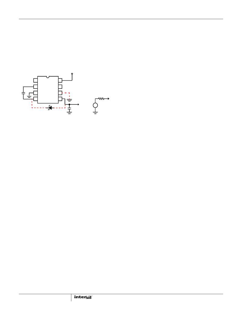
�Simple� Negative� Voltage� Converter�
�charge� the� capacitors� every� cycle.� Equation� 4� shows� a� typical�
�application� where� f� OSC� =� 10kHz� and� C� =� C� 1� =� C� 2� =� 10μF:�
�R� 0� ?� 2x23� +� ---------------------------------------------------� +� 4xESR� C1� +� ESR� C2�
�5� � 10� � 10� � 10�
�The� majority� of� applications� will� undoubtedly� utilize� the�
�ICL7660S� and� ICL7660A� for� generation� of� negative� supply�
�voltages.� Figure� 15� shows� typical� connections� to� provide� a�
�negative� supply� where� a� positive� supply� of� +1.5V� to� +12V� is�
�1�
�3� –� 6�
�R� 0� ?� 46� +� 20� +� 5� � ESR� C�
�(EQ.� 4)�
�available.� Keep� in� mind� that� pin� 6� (LV)� is� tied� to� the� supply�
�negative� (GND)� for� supply� voltage� below� 3.5V.�
�V+�
�Since� the� ESRs� of� the� capacitors� are� reflected� in� the� output�
�impedance� multiplied� by� a� factor� of� 5,� a� high� value� could�
�potentially� swamp� out� a� low� 1/f� PUMP� x� C� 1� term,� rendering� an�
�increase� in� switching� frequency� or� filter� capacitance�
�10μF�
�+�
�-�
�1�
�2�
�3�
�4�
�ICL7660S�
�ICL7660A�
�8�
�7�
�6�
�5�
�-�
�R� O�
�V� OUT�
�ineffective.� Typical� electrolytic� capacitors� may� have� ESRs� as�
�high� as� 10� Ω� .�
�Output� Ripple�
�ESR� also� affects� the� ripple� voltage� seen� at� the� output.� The�
�peak-to-peak� output� ripple� voltage� is� given� by� Equation� 5:�
�V� RIPPLE� ?� ?� -----------------------------------------� +� 2ESR� C2� � I� OUT� ?�
�PUMP� � C� 2�
�-�
�10μF� +�
�V� OUT� =� -V+�
�V+�
�+�
�?� 2� � f� ?�
�1�
�(EQ.� 5)�
�15A.�
�15B.�
�A� low� ESR� capacitor� will� result� in� a� higher� performance�
�FIGURE� 15.� SIMPLE� NEGATIVE� CONVERTER� AND� ITS�
�OUTPUT� EQUIVALENT�
�The� output� characteristics� of� the� circuit� in� Figure� 15� can� be�
�approximated� by� an� ideal� voltage� source� in� series� with� a�
�resistance� as� shown� in� Figure� 15B.� The� voltage� source� has�
�a� value� of� -(V+).� The� output� impedance� (R� O� )� is� a� function� of�
�the� ON� resistance� of� the� internal� MOS� switches� (shown� in�
�output.�
�Paralleling� Devices�
�Any� number� of� ICL7660S� and� ICL7660A� voltage� converters�
�may� be� paralleled� to� reduce� output� resistance.� The� reservoir�
�capacitor,� C� 2� ,� serves� all� devices,� while� each� device� requires�
�its� own� pump� capacitor,� C� 1� .� The� resultant� output� resistance�
�is� approximated� in� Equation� 6:�
�Figure� 14),� the� switching� frequency,� the� value� of� C� 1� and� C� 2� ,�
�and� the� ESR� (equivalent� series� resistance)� of� C� 1� and� C� 2� .� A�
�good� first� order� approximation� for� R� O� is� shown� in�
�Equation� 2:�
�R� OUT� (� of� ICL7660S� )�
�n� (� number� of� devices� )�
�R� OUT� =� ---------------------------------------------------------�
�Cascading� Devices�
�(EQ.� 6)�
�R� 0� ?� 2� (� (� R� SW1� +� R� SW3� +� ESR� C1� )� +� 2� (� R� SW2� +� R� SW4� +� ESR� C1� )� )�
�The� ICL7660S� and� ICL7660A� may� be� cascaded� as� shown� to�
�--------------------------------� +� ESR� C2�
�1�
�f� PUMP� � C� 1�
�(EQ.� 2)�
�produce� larger� negative� multiplication� of� the� initial� supply�
�voltage.� However,� due� to� the� finite� efficiency� of� each� device,�
�the� practical� limit� is� 10� devices� for� light� loads.� The� output�
�2�
�f� OSC�
�f� PUMP� =� --------------�
�(� R� SWX� =� MOSFET� Switch� Resistance� )�
�voltage� is� defined� as� shown� in� Equation� 7:�
�V� OUT� =� –� n� (� V� IN� )�
�(EQ.� 7)�
�R� 0� ?� 2xR� SW� +� --------------------------------� +� 4xESR� C1� +� ESR� C2�
�Combining� the� four� R� SWX� terms� as� R� SW� ,� we� see� in�
�Equation� 3� that:�
�1�
�f� PUMP� � C� 1�
�(EQ.� 3)�
�where� n� is� an� integer� representing� the� number� of� devices�
�cascaded.� The� resulting� output� resistance� would� be�
�approximately� the� weighted� sum� of� the� individual� ICL7660S�
�and� ICL7660A� R� OUT� values.�
�R� SW� ,� the� total� switch� resistance,� is� a� function� of� supply�
�voltage� and� temperature� (see� the� output� source� resistance�
�graphs,� Figures� 2,� 3,� and� 11),� typically� 23� Ω� at� +25°C� and� 5V.�
�Careful� selection� of� C� 1� and� C� 2� will� reduce� the� remaining�
�terms,� minimizing� the� output� impedance.� High� value�
�capacitors� will� reduce� the� 1/(f� PUMP� x� C� 1� )� component,� and� low�
�ESR� capacitors� will� lower� the� ESR� term.� Increasing� the�
�oscillator� frequency� will� reduce� the� 1/(f� PUMP� x� C� 1� )� term,� but�
�may� have� the� side� effect� of� a� net� increase� in� output�
�impedance� when� C� 1� >� 10μF� and� is� not� long� enough� to� fully�
�9�
�Changing� the� ICL7660S� and� ICL7660A� Oscillator�
�Frequency�
�It� may� be� desirable� in� some� applications,� due� to� noise� or� other�
�considerations,� to� alter� the� oscillator� frequency.� This� can� be�
�achieved� simply� by� one� of� several� methods.�
�By� connecting� the� Boost� Pin� (Pin� 1)� to� V+,� the� oscillator�
�charge� and� discharge� current� is� increased� and,� hence,� the�
�oscillator� frequency� is� increased� by� approximately� 3.5� times.�
�The� result� is� a� decrease� in� the� output� impedance� and� ripple.�
�FN3179.7�
�January� 23,� 2013�
�相关PDF资料 |
PDF描述 |
|---|---|
| ICL7662CPA | IC REG SWITCHED CAP DBL INV 8DIP |
| ICL7663ACPA+ | IC REG LDO ADJ 40MA 8-DIP |
| ICL7663SACBAZA | IC REG LDO ADJ 40MA 8SOIC |
| ICL7665ACPA | IC VOLT DETEC DUAL OVR/UND 8-DIP |
| ICL7665SIBA | IC VOLT DETECTOR OVER/UND 8-SOIC |
相关代理商/技术参数 |
参数描述 |
|---|---|
| ICL7660SIPAZ | 功能描述:电荷泵 W/ANNEAL CMOS VAGE CNVRTR IND RoHS:否 制造商:Maxim Integrated 功能:Inverting, Step Up 输出电压:- 1.5 V to - 5.5 V, 3 V to 11 V 输出电流:100 mA 电源电流:1 mA 最大工作温度:+ 70 C 封装 / 箱体:SOIC-8 Narrow 封装:Tube |
| ICL7660SMTV | 制造商:Rochester Electronics LLC 功能描述: |
| ICL7660TV | 制造商:Harris Corporation 功能描述: |
| ICL7661SCBA | 制造商:Rochester Electronics LLC 功能描述:- Bulk |
| ICL7662 WAF | 制造商:Harris Corporation 功能描述: |
发布紧急采购,3分钟左右您将得到回复。