- 您现在的位置:买卖IC网 > PDF目录383107 > IL66 (SIEMENS AG) PHOTODARLINGTON OPTOCOUPLER PDF资料下载
参数资料
| 型号: | IL66 |
| 厂商: | SIEMENS AG |
| 英文描述: | PHOTODARLINGTON OPTOCOUPLER |
| 中文描述: | PHOTODARLINGTON光耦合器 |
| 文件页数: | 1/3页 |
| 文件大小: | 74K |
| 代理商: | IL66 |
5–1
FEATURES
Internal RBE for High Stability
Current Transfer Ratio is Tested
at 2.0 mA and 0.7 mA Input
IL/ILD/ILQ66 Series:
- 1, 100% min. at
- 2, 300% min. at
- 3, 400% min. at
- 4, 500% min. at
Four Available CTR Categories per Package
Type
BV
CEO
>60 V
Standard DIP Packages
Underwriters Lab File #E52744
VDE 0884 Available with Option 1
DESCRIPTION
I
I
I
I
F
F
F
F
=2
=2
=0.7
=2
mA, V
mA, V
mA, V
mA, V
CE
CE
=10 V
=10 V
=10 V
=5 V
CE
CE
IL66, ILD66, and ILQ66 are optically coupled isola-
tors employing Gallium Arsenide infrared emitters
and silicon photodarlington detectors. Switching
can be accomplished while maintaining a high
degree of isolation between driving and load cir-
cuits, with no crosstalk between channels.
Maximum Ratings
Emitter
(Each Channel)
Peak Reverse Voltage........................................ 6 V
Continuous Forward Current.........................60 mA
Power Dissipation at 25
°
C ......................... 100 mW
Derate Linearly from 25
°
C ................... 1.33 mW/
Detector
(Each Channel)
Power Dissipation at 25
°
C Ambient........... 150 mW
Derate Linearly from 25
°
C ..................... 2.0 mW/
Package
Isolation Test Voltage
(t=1 sec.)........................................5300 VAC
Total Package Power Dissipation at 25
IL66.......................................................... 250 mW
ILD66 ....................................................... 400 mW
ILQ66....................................................... 500 mW
Derate Linearly from 25
°
C
IL66...................................................... 3.3 mW/
ILD66 ................................................. 5.33 mW/
ILQ66................................................. 6.67 mW/
Creepage.................................................7 min mm
Clearance ................................................7 min mm
Comparative Tracking Index..............................175
Isolation Resistance
V
IO
=500 V, T
A
=25
°
C................................
V
IO
=500 V, T
A
=100
°
C..............................
Storage Temperature................... –55
Operating Temperature................ –55
Lead Soldering Time at 260
°
C
°
C
RMS
°
C
°
°
°
C
C
C
≥
≥
10
10
12
11
°
°
C
C
°
°
C to +125
C to +100
°
C ....................10 sec.
V
D E
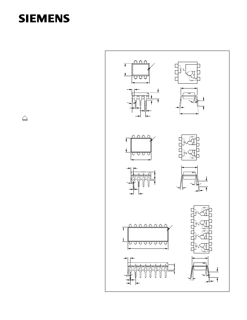
Dimensions in inches (mm)
.010 (.25)
.014 (.35)
.300 (7.62)
.347 (8.82)
.110 (2.79)
.130 (3.30)
.150 (3.81)
.020 (.051) min.
.031 (0.80)
.035 (0.90)
.100 (2.54) Typ.
.300 (7.62)
Typ.
(.min.
.018 (0.45)
.022 (0.55)
.335 (8.50)
.343 (8.70)
6
5
4
1
2
3
°
18
°
t4
.255 (6.48)
.268 (6.81)
3
4
6
5
.379 (9.63)
.390 (9.91)
.030 (.76)
.045 (1.14)
4
°
Typ.
.100 (2.54) Typ.
10
°
Typ.
3
°
–9
°
.305
T
yp.
(7.75)
T
yp.
.018 (.46)
.022 (.56)
.008 (.20)
.012 (.30)
.115 (2.92)
.135 (3.43)
1
2
8
7
.130 (3.30)
.150 (3.81)
.030 (.76 )
.040 (1.02)
1
2
3
6
5
4
Anode
Cathode
NC
Base
Collector
Emitter
Anode
Cathode
Cathode
Anode
Emitter
Collector
Collector
Emitter
1
2
3
4
8
7
6
5
Anode
Cathode
Cathode
Anode
Emitter
Collector
Collector
Emitter
1
2
3
4
5
6
7
8
16
15
14
13
12
11
10
9
Emitter
Collector
Collector
Emitter
Anode
Cathode
Cathode
Anode
.248 (6.30)
.256 (6.50)
.255 (6.48)
.268 (6.81)
.779 (19.77 )
.790 (20.07)
Pin
One
I.D.
.130 (3.30)
.150 (3.81)
.030 (.76 )
.040 (1.02)
.030 (.76)
.045 (1.14)
4
°
Typ.
.100 (2.54) Typ.
.018 (.46)
.022 (.56)
10
°
Typ.
3
°
–9
°
.305 Typ.
(7.75) Typ.
.008 (.20)
.012 (.30)
.115 (2.92)
.135 (3.43)
Pin One I.D.
Pin One I.D.
SINGLE CHANNEL
DUAL CHANNEL
QUAD CHANNEL
PHOTODARLINGTON OPTOCOUPLER
IL66 SERIES
ILD66 SERIES
ILQ 66 SERIES
相关PDF资料 |
PDF描述 |
|---|---|
| ILD766 | BIDIRECTIONAL INPUT DARLINGTON OPTOCOUPLERS |
| IL766 | SMT Rotary Dip |
| ILH100 | HERMETIC PHOTOTRANSISTOR OPTOCOUPLER |
| ILH200 | HERMETIC PHOTOTRANSISTOR DUAL CHANNEL OPTOCOUPLER |
| ILQ32 | PHOTODARLINGTON OPTOCOUPLER |
相关代理商/技术参数 |
参数描述 |
|---|---|
| IL66_07 | 制造商:VISHAY 制造商全称:Vishay Siliconix 功能描述:Optocoupler, Photodarlington Output, with Internal RBE (Single, Dual, Quad Channel) |
| IL66-1 | 功能描述:晶体管输出光电耦合器 Photodarlington Out Single CTR >100% RoHS:否 制造商:Vishay Semiconductors 输入类型:DC 最大集电极/发射极电压:70 V 最大集电极/发射极饱和电压:0.4 V 绝缘电压:5300 Vrms 电流传递比:100 % to 200 % 最大正向二极管电压:1.65 V 最大输入二极管电流:60 mA 最大集电极电流:100 mA 最大功率耗散:100 mW 最大工作温度:+ 110 C 最小工作温度:- 55 C 封装 / 箱体:DIP-4 封装:Bulk |
| IL66-1X016 | 制造商:Vishay Angstrohm 功能描述:Optocoupler DC-IN 1-CH Darlington With Base DC-OUT 4-Pin PDIP 制造商:Vishay Semiconductors 功能描述:DIP-4 CPL DARLINGTON CTR>100% VDE -E - Tape and Reel |
| IL66-2 | 制造商:VISHAY 制造商全称:Vishay Siliconix 功能描述:Optocoupler, Photodarlington Output, with Internal RBE (Single, Dual, Quad Channel) |
| IL66-3 | 功能描述:晶体管输出光电耦合器 Photodarlington Out Single CTR >400% RoHS:否 制造商:Vishay Semiconductors 输入类型:DC 最大集电极/发射极电压:70 V 最大集电极/发射极饱和电压:0.4 V 绝缘电压:5300 Vrms 电流传递比:100 % to 200 % 最大正向二极管电压:1.65 V 最大输入二极管电流:60 mA 最大集电极电流:100 mA 最大功率耗散:100 mW 最大工作温度:+ 110 C 最小工作温度:- 55 C 封装 / 箱体:DIP-4 封装:Bulk |
发布紧急采购,3分钟左右您将得到回复。