- 您现在的位置:买卖IC网 > PDF目录67720 > IMISC643AYB PROC SPECIFIC CLOCK GENERATOR, PDSO48 PDF资料下载
参数资料
| 型号: | IMISC643AYB |
| 元件分类: | 时钟产生/分配 |
| 英文描述: | PROC SPECIFIC CLOCK GENERATOR, PDSO48 |
| 封装: | SSOP-48 |
| 文件页数: | 8/12页 |
| 文件大小: | 138K |
| 代理商: | IMISC643AYB |
SC643
I
2C Clock Generator for 3 DIMM, Pentium
II Designs
Approved Product
INTERNATIONAL MICROCIRCUITS, INC. 525 LOS COCHES ST.
Rev.1.6
6/20/97
MILPITAS, CA 95035. TEL: 408-263-6300. FAX 408-263-6571
Page 5 of 12
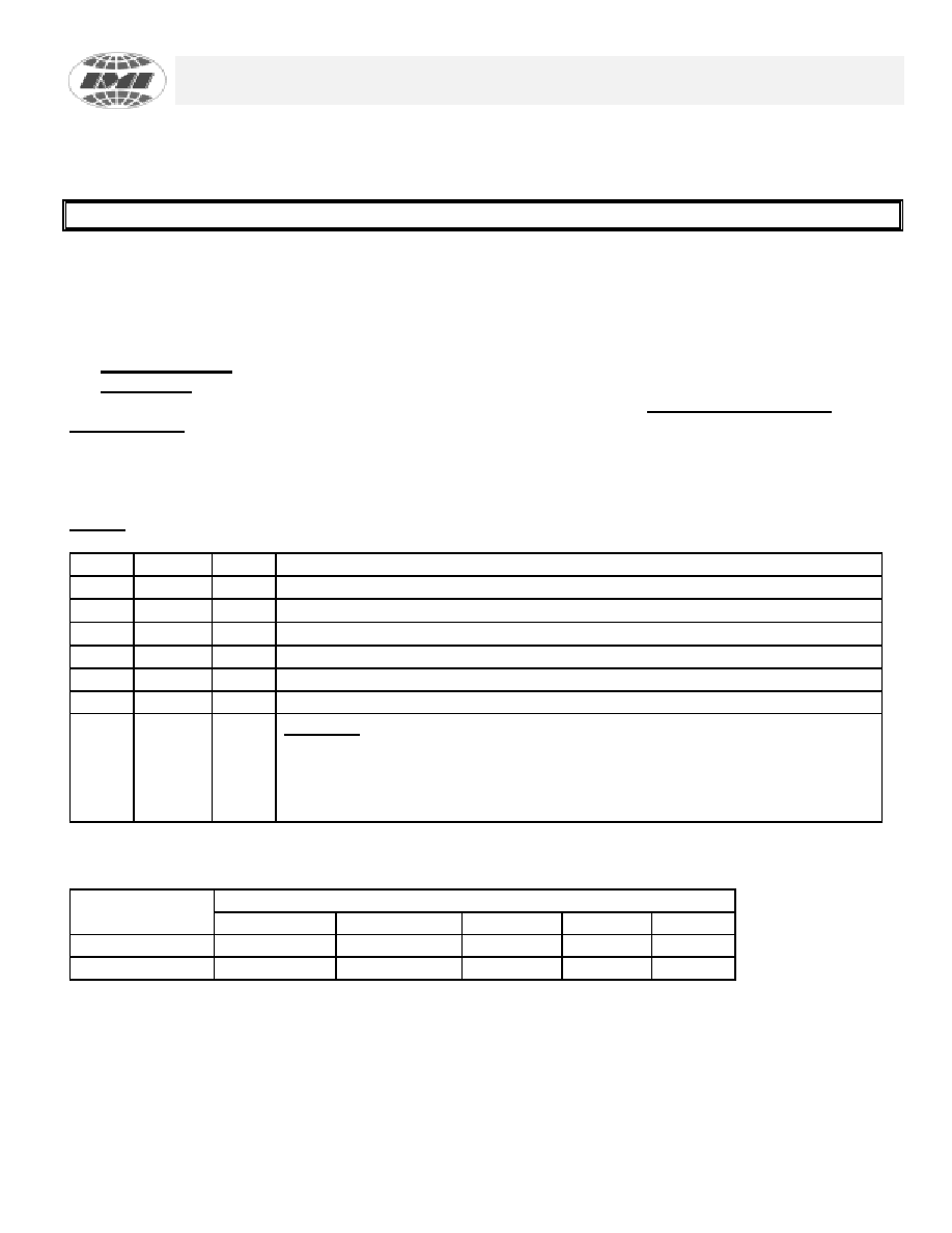
SERIAL CONTROL REGISTERS
NOTE: The Pin# column lists the affected pin number where applicable. The @Pup column gives the state
at true power up. Bytes are set to the values shown only on true power up, and not when the PWR_DWN#
pin is activated.
Following the acknowledge of the Address Byte (D2), two additional bytes must be sent:
1) “Command Code “ byte, and
2) “Byte Count” byte.
Although the data (bits) in these two bytes are considered “don’t care”, they must be sent and will be
acknowledged.
After the Command Code and the Count bytes have been acknowledged, the below desrcibed sequence
(Byte 0, Byte 1, Byte2, ....) will be valid and acknowledged.
Byte 0: Frequency, Function Select Register (1 = enable, 0 = Stopped)
Bit
@Pup
Pin#
Description
7
1
*
FTS (for frequency table selection by software via I2C)
61
*
S2
(for frequency table selection by software via I2C)
51
*
S1
(for frequency table selection by software via I2C)
41
*
S0
(for frequency table selection by software via I2C)
3
0
*
enables freq. selection by hardware (set to 0) or software I2C (set to 1)
2
x
n/a
Reserved for future Spectrum Spread function
1
0
*
Bit1 Bit0
1
1 Tri-State
1
0 Reserved for future Spectrum Spread function
0
1 Reserved for future Spectrum Spread function
0
0 Normal
Function Table
Function
Outputs
Description
CPU
PCI
SDRAM
Ref
IOAPIC
Tri-State
Hi-Z
Normal
see table
CPU
14.318
相关PDF资料 |
PDF描述 |
|---|---|
| IMISC670DYB | PROC SPECIFIC CLOCK GENERATOR, PDSO48 |
| IMISG522BXB | OTHER CLOCK GENERATOR, PDSO16 |
| IMISG522BX | 120 MHz, OTHER CLOCK GENERATOR, PDSO16 |
| IMISG524BX | 120 MHz, OTHER CLOCK GENERATOR, PDSO16 |
| IMISG570CYB | PROC SPECIFIC CLOCK GENERATOR, PDSO48 |
相关代理商/技术参数 |
参数描述 |
|---|---|
| IMISC652EYB | 制造商:未知厂家 制造商全称:未知厂家 功能描述:CPU System Clock Generator |
| IMISC660 | 制造商:未知厂家 制造商全称:未知厂家 功能描述:Clocks and Buffers |
| IMISC660EYB | 制造商:International Microcircuits Inc 功能描述:LOW SKEW CLOCK DRIVER, PDSO28 |
| IMISC670DYB | 制造商:未知厂家 制造商全称:未知厂家 功能描述:CPU System Clock Generator |
| IMISC671CTB | 制造商:未知厂家 制造商全称:未知厂家 功能描述:CPU System Clock Generator |
发布紧急采购,3分钟左右您将得到回复。