- 您现在的位置:买卖IC网 > PDF目录1810 > IR3870MTRPBF (International Rectifier)IC REG BUCK SYNC ADJ 10A 15QFN PDF资料下载
参数资料
| 型号: | IR3870MTRPBF |
| 厂商: | International Rectifier |
| 文件页数: | 16/20页 |
| 文件大小: | 0K |
| 描述: | IC REG BUCK SYNC ADJ 10A 15QFN |
| 产品培训模块: | SupIRBuck? Family and POL Design Tools Overview |
| 标准包装: | 4,000 |
| 系列: | SupIRBuck™ |
| 类型: | 降压(降压) |
| 输出类型: | 可调式 |
| 输出数: | 1 |
| 输出电压: | 0.5 V ~ 12 V |
| 输入电压: | 3 V ~ 26 V |
| 频率 - 开关: | 可调至 1MHz |
| 电流 - 输出: | 10A |
| 同步整流器: | 是 |
| 工作温度: | 0°C ~ 125°C |
| 安装类型: | 表面贴装 |
| 封装/外壳: | 16-PowerVQFN |
| 包装: | 带卷 (TR) |
| 供应商设备封装: | PQFN(5x6) |
�� �
�
�IR3870MPBF�
�This� capacitor� has� 9m� ?� ESR� which� leaves�
�margin� for� the� voltage� drop� of� the� ESL� during�
�load� step� up.� The� typical� ESL� for� this� capacitor� is�
�around� 2nH.� Refer� to� Output� Capacitor� Selection�
�section� for� all� ceramic� capacitor� solution.�
�LAYOUT� RECOMMENDATION�
�Bypass� Capacitor:�
�One� 1uF� high� quality� ceramic� capacitor� should�
�be� placed� as� near� VCC� pin� as� possible.� The�
�other� end� of� capacitor� can� be� connected� to� a�
�via� or� connected� directly� to� GND� plane.� Use� a�
�GND� plane� instead� of� thin� trace� to� the� GND� pin�
�because� this� thin� traces� have� too� much� higher�
�impedance.� A� 1uF� is� recommended� for� both�
�V5� and� PVCC� and� repeat� the� layout� procedure�
�above� for� those� signals.�
�Charge� Pump:�
�We� recommend� that� D1,� D2� and� C� CPO� be�
�placed� as� close� to� the� CPO� and� PVCC� pins� as�
�possible.� If� those� components� can� not� be�
�placed� on� the� same� layer� as� IR3870,� a�
�minimum� of� two� vias� are� needed� for� the�
�connection� of� C� CPO� and� CPO� pin� and� the�
�connection� of� D2� and� PVCC.�
�Boot� Circuit:�
�C� BOOT� should� be� placed� near� the� BOOT� and�
�PHASE� pins� to� reduce� the� impedance� when� the�
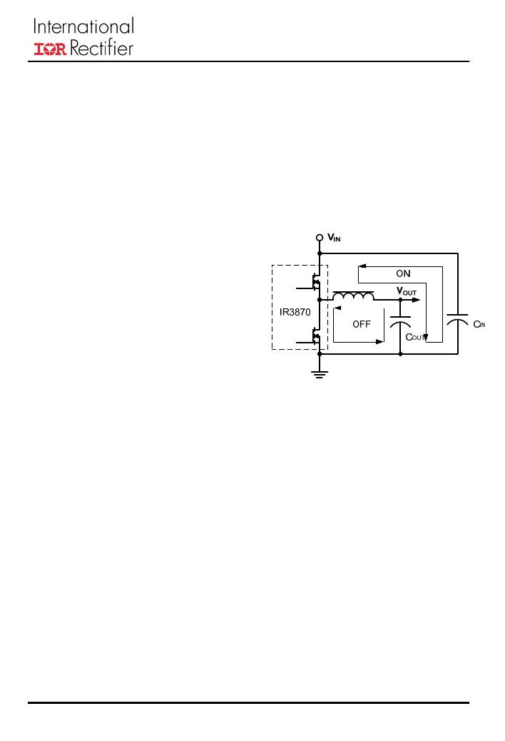
�The� purpose� of� the� tight� loop� from� the� input�
�ceramic� capacitor� is� to� suppress� the� high�
�frequency� (10MHz� range)� switching� noise� and�
�reduce� Electromagnetic� Interference� (EMI).� If�
�this� path� has� high� inductance,� the� circuit� will�
�cause� voltage� spikes� and� ringing,� and� increase�
�the� switching� loss.� The� off� time� path� has� low�
�AC� and� high� average� DC� current.� Therefore,� it�
�should� be� laid� out� with� a� tight� loop� and� wide�
�trace� at� both� ends� of� the� inductor.� Lowering� the�
�loop� resistance� reduces� the� power� loss.� The�
�typical� resistance� value� of� 1-ounce� copper�
�thickness� is� 0.5m� ?� per� square� inch.�
�Figure� 19.� Current� Path� of� Power� Stage�
�upper� MOSFET� turns� on.� D� BOOT� does� not� need�
�to� be� close� to� C� BOOT� because� the� average�
�current� to� charge� C� BOOT� is� small� during� the� on�
�time� of� lower� MOSFET.�
�Power� Stage:�
�Figure� 19� shows� the� flowing� current� path� for�
�the� on� and� off� periods.� The� on� time� path� has�
�low� average� DC� current� with� high� AC� current.�
�Therefore,� it� is� recommended� to� place� the� input�
�ceramic� capacitor,� upper,� and� lower� MOSFET�
�in� a� tight� loop� as� shown� in� Figure� 19.�
�16�
�相关PDF资料 |
PDF描述 |
|---|---|
| IR3871MTR1PBF | IC REG BUCK SYNC ADJ 8A 17QFN |
| IR3876MTRPBF | IC REG BUCK SYNC ADJ 12A 17QFN |
| IR5001SPBF | IC CTRLR/MOSFET UNIV N-CH 8SOIC |
| IR51H310 | IC HALF BRIDGE SELF-OSC 9-SIP |
| IR51HD420 | IC HALF BRIDGE SELF-OSC 9-SIP |
相关代理商/技术参数 |
参数描述 |
|---|---|
| IR3871MPBF | 制造商:IRF 制造商全称:International Rectifier 功能描述:8A HIGHLY INTEGRATED WIDE-INPUT VOLTAGE, SYNCHRONOUS BUCK REGULATOR |
| IR3871MTR1PBF | 功能描述:直流/直流开关调节器 8A SupIRBuck Reg 1000kHz, 3.0-26V in RoHS:否 制造商:International Rectifier 最大输入电压:21 V 开关频率:1.5 MHz 输出电压:0.5 V to 0.86 V 输出电流:4 A 输出端数量: 最大工作温度: 安装风格:SMD/SMT 封装 / 箱体:PQFN 4 x 5 |
| IR3871MTRPBF | 功能描述:直流/直流开关调节器 8A SupIRBuck Reg 1000kHz, 3.0-26V in RoHS:否 制造商:International Rectifier 最大输入电压:21 V 开关频率:1.5 MHz 输出电压:0.5 V to 0.86 V 输出电流:4 A 输出端数量: 最大工作温度: 安装风格:SMD/SMT 封装 / 箱体:PQFN 4 x 5 |
| IR3876MBF | 制造商:IRF 制造商全称:International Rectifier 功能描述:12A HIGHLY INTEGRATED WIDE-INPUT VOLTAGE, SYNCHRONOUS BUCK REGULATOR |
| IR3876MPBF | 制造商:IRF 制造商全称:International Rectifier 功能描述:12A HIGHLY INTEGRATED WIDE-INPUT VOLTAGE, SYNCHRONOUS BUCK REGULATOR |
发布紧急采购,3分钟左右您将得到回复。