- 您现在的位置:买卖IC网 > PDF目录1812 > IRU3065CLTR (International Rectifier)IC REG CTRLR INV PWM SOT23-6 PDF资料下载
参数资料
| 型号: | IRU3065CLTR |
| 厂商: | International Rectifier |
| 文件页数: | 10/15页 |
| 文件大小: | 0K |
| 描述: | IC REG CTRLR INV PWM SOT23-6 |
| 标准包装: | 1 |
| PWM 型: | 控制器 |
| 输出数: | 1 |
| 频率 - 最大: | 1.5MHz |
| 占空比: | 100% |
| 电源电压: | 5V |
| 降压: | 无 |
| 升压: | 无 |
| 回扫: | 无 |
| 反相: | 是 |
| 倍增器: | 无 |
| 除法器: | 无 |
| Cuk: | 无 |
| 隔离: | 无 |
| 工作温度: | 0°C ~ 70°C |
| 封装/外壳: | SOT-23-6 |
| 包装: | 剪切带 (CT) |
| 配用: | IRDC3065-ND - LOW PWR SWTCH REG REF DESIGN KIT |
| 其它名称: | *IRU3065CLTR IRU3065CLCT |
�� �
�
�IRU3065(PbF)�
�THEORETICAL� OPERATION�
�Operation-Regulation� Mode�
�V� g� a� te�
�reference� of� the� chip,� which� is� set� to� be� 150mV� (for�
�Vcc=5V),� the� flip-flop� is� reset� and� the� PMOS� is� turned�
�off.� The� inductor� current� is� discharged� through� diode�
�D2� to� the� load.� The� load� voltage� increases.� When� the�
�inductor� current� decreases� to� zero,� the� output� current�
�is� supplied� by� the� output� capacitor� and� the� output� volt-�
�age� decreases� until� next� cycle� starts.� In� this� mode,� the�
�voltage� at� V� SEN� pin� is� controlled� near� zero.� Therefore,�
�the� output� voltage� is� regulated� at:�
�V� in�
�-V� OUT� =�
�R3�
�R2�
�� V� REF�
�V� o� lta� g� e� a� cro� ss�
�th� e� in� d� u� cto� r�
�V� out� ?� V� D�
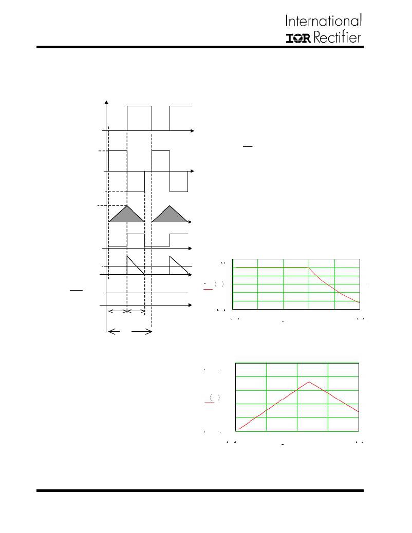
�In� the� evaluation� board,� the� output� voltage� is� regulated�
�at� -5V,� as� shown� in� figure� 7.� The� steady� state� of� the�
�converter� should� be� operated� in� this� mode.� One� feature�
�in� this� mode� is� that� the� shaded� inductor� current� in� fig-�
�ure� 18� stays� unchanged.� The� average� output� diode� cur-�
�In� d� u� cto� r�
�cu� rre� n� t�
�I� peak�
�rent� equals� output� current.� When� the� switching� period�
�decreases� and� frequency� goes� up,� the� average� diode�
�current� increases� to� support� more� output� current.� The�
�O� u� tp� u� t� o� f� cu� rre� n� t�
�co� m� p� a� ra� to� r�
�switching� frequency� increases� linearly� when� the� load�
�current� increases� as� shown� in� figure� 20.�
�O� u� tp� u� t� d� io� d� e�
�cu� rre� n� t�
�I� out�
�5�
�6�
�5�
�4�
�?� V� out�
�=�
�R 3�
�R� 2�
�?� V� ref�
�V� out� I� out�
�3�
�2�
�1�
�0.75�
�0�
�0�
�0.16�
�0.32�
�0.48�
�0.64�
�0.8�
�t� on�
�t� 1�
�0.02�
�I� out�
�0.8�
�T� s�
�Figure� 19� -� Theoretical� output� voltage� (-V� OUT� )�
�versus� output� current� for� IRU3065� controlled� buck�
�boost� evaluation� board.(assume� VIsen=0.2V)�
�Figure� 18� -� Operation� waveforms� of� IRU3065� con-�
�1.083� .� 10�
�1.5� .� 10�
�6�
�6�
�trolled� buck� boost� converter� at� regulation� mode.�
�1.2� .� 10�
�6�
�In� general,� IRU3065� controlled� buck� boost� converter�
�9� .� 10�
�5�
�is� operated� in� two� modes� depending� on� the� load� cur-�
�rent.� When� the� load� current� is� small,� the� buck� boost�
�f� s� I� out�
�6� .� 10�
�5�
�3� .� 10�
�4.583� .� 10�
�I� out�
�operated� in� first� mode� (regulation� mode).� The� operation�
�waveforms� are� shown� in� figure� 18.� In� this� mode,� the�
�inductor� current� in� the� buck� converter� is� discontinuous.�
�Basic� Operation�
�When� the� voltage� at� V� SEN� pin� is� below� zero,� the� flip-flop�
�inside� the� IC� is� set� and� the� V� GATE� pin� output� low,� which�
�trigger� the� PMOS� in� the� power� stage,� the� output� induc-�
�tor� current� increases� from� zero.� When� sensed� inductor�
�current� voltage� at� I� SEN� pin� reaches� the� internal� current�
�5�
�4�
�0�
�0� 0.2� 0.4� 0.6�
�0.02�
�Figure� 20� -� Theoretical� switching� frequency� versus�
�output� current� for� evaluation� board.(assume�
�VIsen=0.2V)�
�0.8�
�0.8�
�10�
�www.irf.com�
�相关PDF资料 |
PDF描述 |
|---|---|
| IRU3137CSTRPBF | IC REG CTRLR BUCK PWM VM 8-SOIC |
| IRU3138CSTRPBF | IC REG CTRLR BUCK PWM VM 14-SOIC |
| IRU3146CFTR | IC REG CTRLR BUCK PWM VM 28TSSOP |
| IRU431LCL5TR | IC VREF SHUNT PREC ADJ SOT-23-5 |
| ISL1801IVZ | IC CONV SOLAR PWR 48TSSOP |
相关代理商/技术参数 |
参数描述 |
|---|---|
| IRU3065CLTRPBF | 制造商:IRF 制造商全称:International Rectifier 功能描述:POSITIVE TO NEGATIVE DC TO DC CONTROLLER |
| IRU3072C | 制造商:IRF 制造商全称:International Rectifier 功能描述:20-PIN SYNCHRONOUS PWM CONTROLLER/ 3 LDO CONTROLLER |
| IRU3072CH | 制造商:IRF 制造商全称:International Rectifier 功能描述:20-PIN SYNCHRONOUS PWM CONTROLLER/ 3 LDO CONTROLLER |
| IRU3072CHTR | 制造商:International Rectifier 功能描述:VOLT MODE PWM CNTRLR 0.8V TO 24.75V/1.5V/1.8V/2.5V 1A 20MLPQ - Tape and Reel |
| IRU3073 | 制造商:IRF 制造商全称:International Rectifier 功能描述:SYNCHRONOUS PWM CONTROLLER WITH OVER-CURRENT PROTECTION / LDO CONTROLLER |
发布紧急采购,3分钟左右您将得到回复。