- 您现在的位置:买卖IC网 > PDF目录1812 > IRU3065CLTR (International Rectifier)IC REG CTRLR INV PWM SOT23-6 PDF资料下载
参数资料
| 型号: | IRU3065CLTR |
| 厂商: | International Rectifier |
| 文件页数: | 11/15页 |
| 文件大小: | 0K |
| 描述: | IC REG CTRLR INV PWM SOT23-6 |
| 标准包装: | 1 |
| PWM 型: | 控制器 |
| 输出数: | 1 |
| 频率 - 最大: | 1.5MHz |
| 占空比: | 100% |
| 电源电压: | 5V |
| 降压: | 无 |
| 升压: | 无 |
| 回扫: | 无 |
| 反相: | 是 |
| 倍增器: | 无 |
| 除法器: | 无 |
| Cuk: | 无 |
| 隔离: | 无 |
| 工作温度: | 0°C ~ 70°C |
| 封装/外壳: | SOT-23-6 |
| 包装: | 剪切带 (CT) |
| 配用: | IRDC3065-ND - LOW PWR SWTCH REG REF DESIGN KIT |
| 其它名称: | *IRU3065CLTR IRU3065CLCT |
�� �
�
�IRU3065(PbF)�
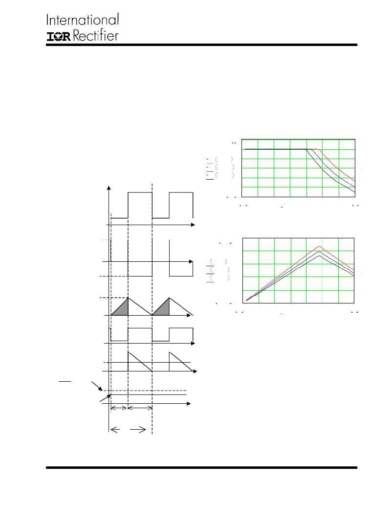
�Power� Limit� Mode�
�When� the� output� current� continuous� increases,� the�
�switching� period� continuous� decreases� until� the� induc-�
�tor� current� goes� into� the� boundary� of� discontinuous� and�
�continuous� mode� as� shown� in� Figure� 21.� Then� the�
�IRU3065� controlled� buck� boost� converter� goes� into� power�
�limit� mode.� In� this� mode,� the� output� power� is� limited.�
�The� output� voltage� is� no� longer� regulated.� The� output�
�voltage� decreases� when� the� load� current� increases� as�
�shown� in� Figure� 19.� In� this� mode,� the� shaded� inductor�
�current� in� Figure� 18� keeps� same.� The� turn� off� time� pe-�
�Influence� of� System� Parameters�
�From� above� section,� there� is� a� critical� output� current�
�I� OCP� .� When� the� output� current� is� larger� than� I� OCP� ,� the�
�output� voltage� is� out� of� the� regulation� and� switching� fre-�
�quency� starts� to� decreases.� When� output� current� equals�
�I� OCP� ,� the� frequency� reaches� its� maximum� f� S(MAX)� .� Analy-�
�sis� shows� that� the� current� I� OCP� and� maximum� frequency�
�f� S(MAX)� strongly� depends� on� the� parameters� such� as� cur-�
�rent� sensing� resistor� R� S� and� inductance� L� as� well� as� the�
�input� and� output� voltage.�
�riod� is� dependent� on� the� output� voltage.� When� the� out-�
�put� current� increases,� the� output� voltage� decreases� and�
�it� takes� more� time� for� the� inductor� current� to� reset� from�
�peak� current� to� zero.� Therefore,� the� turn� off� period� in-�
�creases.� Overall� the� switching� frequency� decreases�
�when� load� current� increases� as� shown� in� Figure� 20.�
�V� out� I� out� ,� 0.1� .� ?�
�V� out� I� out� ,� 0.11� .� ?�
�V� out� I� out� ,� 0.12� .� ?�
�5�
�6�
�5�
�4�
�3�
�2�
�1�
�Vgate�
�0.452�
�0�
�0�
�0.02�
�0.1�
�0.2�
�0.3�
�I� out�
�0.4�
�0.5�
�0.6�
�0.7�
�0.7�
�Figure� 22� -� Theoretical� output� voltage� versus� output�
�current� with� different� current� sensing� resistor� R� S.�
�1.5� .� 10�
�1.3� .� 10�
�1.2� .� 10�
�Vin�
�Voltage� across�
�6�
�6�
�6�
�9� .� 10�
�6� .� 10�
�3� .� 10�
�the� inductor�
�V� out� ?� V� D�
�f� s� I� out� ,� 1� .� μ� H�
�f� s� I� out� ,� 1.1� .� μ� H�
�f� s� I� out� ,� 1.2� .� μ� H�
�5�
�5�
�5�
�Inductor�
�I� peak�
�4.583� .� 10� 4�
�0�
�0�
�0.1�
�0.2�
�0.3�
�0.4�
�0.5�
�0.6�
�0.7�
�current�
�0.02�
�I� out�
�0.7�
�?� V� ref�
�Output� of� current�
�comparator�
�Output� diode�
�current� I� out�
�R 3�
�R� 2�
�?� V� out�
�t� on�
�t� 1�
�Figure� 23� -� Theoretical� operation� switching� frequency�
�versus� output� current� with� different� inductance� L.�
�Figure� 22� shows� the� calculated� output� voltage� versus�
�output� current� with� different� current� sensing� resistor� R� S� .�
�With� different� R� S� ,� the� critical� current� IOCP� varies,� and�
�the� power� process� ability� changes.� Figure� 23� shows�
�the� calculated� operation� switching� frequency� versus�
�output� current� with� different� inductance� L� when� R� S� =0.1� ?� .�
�The� inductance� L� determines� the� maximum� switching�
�frequency� of� the� buck� boost� converter.�
�T� s�
�Figure� 21� -� Operation� waveforms� of� IRU3065� con-�
�trolled� buck� boost� converter� at� power� limit� mode.�
�www.irf.com�
�11�
�相关PDF资料 |
PDF描述 |
|---|---|
| IRU3137CSTRPBF | IC REG CTRLR BUCK PWM VM 8-SOIC |
| IRU3138CSTRPBF | IC REG CTRLR BUCK PWM VM 14-SOIC |
| IRU3146CFTR | IC REG CTRLR BUCK PWM VM 28TSSOP |
| IRU431LCL5TR | IC VREF SHUNT PREC ADJ SOT-23-5 |
| ISL1801IVZ | IC CONV SOLAR PWR 48TSSOP |
相关代理商/技术参数 |
参数描述 |
|---|---|
| IRU3065CLTRPBF | 制造商:IRF 制造商全称:International Rectifier 功能描述:POSITIVE TO NEGATIVE DC TO DC CONTROLLER |
| IRU3072C | 制造商:IRF 制造商全称:International Rectifier 功能描述:20-PIN SYNCHRONOUS PWM CONTROLLER/ 3 LDO CONTROLLER |
| IRU3072CH | 制造商:IRF 制造商全称:International Rectifier 功能描述:20-PIN SYNCHRONOUS PWM CONTROLLER/ 3 LDO CONTROLLER |
| IRU3072CHTR | 制造商:International Rectifier 功能描述:VOLT MODE PWM CNTRLR 0.8V TO 24.75V/1.5V/1.8V/2.5V 1A 20MLPQ - Tape and Reel |
| IRU3073 | 制造商:IRF 制造商全称:International Rectifier 功能描述:SYNCHRONOUS PWM CONTROLLER WITH OVER-CURRENT PROTECTION / LDO CONTROLLER |
发布紧急采购,3分钟左右您将得到回复。