- 您现在的位置:买卖IC网 > PDF目录384512 > IS82C52 (INTERSIL CORP) CMOS Serial Controller Interface PDF资料下载
参数资料
| 型号: | IS82C52 |
| 厂商: | INTERSIL CORP |
| 元件分类: | 微控制器/微处理器 |
| 英文描述: | CMOS Serial Controller Interface |
| 中文描述: | 1 CHANNEL(S), 1M bps, SERIAL COMM CONTROLLER, PQCC28 |
| 封装: | PLASTIC, LCC-28 |
| 文件页数: | 6/19页 |
| 文件大小: | 255K |
| 代理商: | IS82C52 |
5-6
disabled from the SDO output pin. The Receiver Enable bit
gates off the input to the receiver circuitry when in the false
state.
Modem Interrupt Enable will permit any change in modem
status line inputs (CTS, DSR) to cause an interrupt when
this bit is enabled. Bit D7 must always be written to with a
logic zero to insure correct 82C52 operation.
UART Status Register (USR)
The USR provides a single register that the controlling sys
tem can examine to determine if errors have occurred or if
other status changes in the 82C52 require attention. For this
reason, the USR is usually the first register read by the CPU
to determine the cause of an interrupt or to poll the status of
the 82C52.
Three error flags OE, FE and PE report the status of any
error conditions detected in the receiver circuitry. These
error flags are updated with every character received during
reception of the stop bits. The Overrun Error (OE) indicates
that a character in the Receiver Register has been received
and cannot be transferred to the Receiver Buffer Register
(RBR) because the RBR was not read by the CPU. Framing
Error (FE) indicates that the last character received in the
RBR contained improper stop bits. This could be caused by
the absence of the required stop bit(s) or by a stop bit(s) that
was too short to be properly detected. Parity Error (PE) indi-
cates that the last character received in the RBR contained a
parity error based on the programmed parity of the receiver
and the calculated parity of the received character data and
parity bits.
The Received Break (RBRK) status bit indicates that the last
character received was a break character. A break character
would be considered to be an invalid data character in that
the entire character including parity and stop bits are a logic
zero.
The Modem Status bit is set whenever a transition is
detected on any of the Modem input lines (CTS or DSR). A
subsequent read of the Modem Status Register will show the
state of these two signals. Assertion of this bit will cause an
interrupt (INTR) to be generated if the MIEN and INTEN bits
in the MCR register are enabled.
The Transmission Complete (TC) bit indicates that both the
TBR and Transmitter Registers are empty and the 82C52
has completed transmission of the last character it was com-
manded to transmit. The assertion of this bit will cause an
interrupt (INTR) if the INTEN bit in the MCR register is true.
The Transmitter Buffer Register Empty (TBRE) bit indicates
that the TBR register is empty and ready to receive another
character.
The Data Ready (DR) bit indicates that the RBR has been
loaded with a received character (including Break) and that
the CPU may access this data.
Assertion of the TBRE or DR bits do not affect the INTR
logic and associated INTR output pin since the 82C52 has
been designed to provide separate requests via the DR and
TBRE output pins. If a single interrupt for any status change
in the 82C52 is desired this can be accomplished by using
an 82C59A Interrupt controller with DR, TBRE, and INTR as
inputs. (See Figure 11).
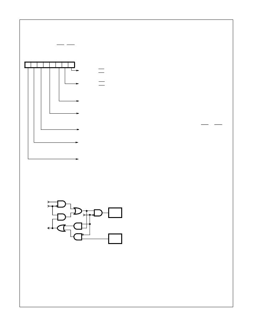
D7 D6 D5 D4 D3 D2 D1 D0
Request
to Send
(RTS)
0 = RTS Output High
1 = RTS Output Low
Data
Terminal
Ready
(DTR)
0 = DTR Output High
1 = DTR Output Low
Interrupt
Enable
(INTEN)
1 = Interrupts Enabled
0 = interrupts Disabled
Mode
Select
00 = Normal
01 = Transmit Break
10 = Echo Mode
11 = Loop Test Mode
Receiver
Enable
(REN)
0 = Not Enabled
1 = Enabled
Modem
Interrupt
Enable
(MIEN)
0 = Not Enabled
1 = Enabled
Must be Set to a Logic 0 for
Normal 82C52 Operation
See Modem Status Register description for a description of
register flag images with respect to output pins.
FIGURE 3. MCR
FIGURE 4. LOOP AND ECHO MODE FUNCTIONALITY
SERIAL DATA
FROM
TRANSMITTER
REGISTER
ECHO MODE
SERIAL DATA
TO RECEIVER
REGISTER
SDO
PIN 15
SDI
PIN 25
LOOP
MODE
82C52
相关PDF资料 |
PDF描述 |
|---|---|
| IS82C54 | CMOS Programmable Interval Timer |
| IS82C54-10 | CMOS Programmable Interval Timer |
| IS82C54-12 | CMOS Programmable Interval Timer |
| IS82C82 | CMOS Octal Latching Bus Driver |
| IS82C83H | CMOS Octal Latching Inverting Bus Driver |
相关代理商/技术参数 |
参数描述 |
|---|---|
| IS82C52/TR100/BAE | 制造商:Intersil Corporation 功能描述:PERIPH UART/BRG 5V 16MHZ 28PLCC IND - Tape and Reel |
| IS82C5296 | 制造商:Rochester Electronics LLC 功能描述:- Bulk |
| IS82C52R2490 | 制造商:Rochester Electronics LLC 功能描述:- Bulk |
| IS82C52Z | 功能描述:UART 接口集成电路 W/ANNEAL PERIPH /BRG 5V 16MHZ RoHS:否 制造商:Texas Instruments 通道数量:2 数据速率:3 Mbps 电源电压-最大:3.6 V 电源电压-最小:2.7 V 电源电流:20 mA 最大工作温度:+ 85 C 最小工作温度:- 40 C 封装 / 箱体:LQFP-48 封装:Reel |
| IS82C52Z96 | 功能描述:UART 接口集成电路 W/ANNEAL PERIPH /BRG 5V 16MHZ RoHS:否 制造商:Texas Instruments 通道数量:2 数据速率:3 Mbps 电源电压-最大:3.6 V 电源电压-最小:2.7 V 电源电流:20 mA 最大工作温度:+ 85 C 最小工作温度:- 40 C 封装 / 箱体:LQFP-48 封装:Reel |
发布紧急采购,3分钟左右您将得到回复。