- 您现在的位置:买卖IC网 > PDF目录384512 > IS82C52 (INTERSIL CORP) CMOS Serial Controller Interface PDF资料下载
参数资料
| 型号: | IS82C52 |
| 厂商: | INTERSIL CORP |
| 元件分类: | 微控制器/微处理器 |
| 英文描述: | CMOS Serial Controller Interface |
| 中文描述: | 1 CHANNEL(S), 1M bps, SERIAL COMM CONTROLLER, PQCC28 |
| 封装: | PLASTIC, LCC-28 |
| 文件页数: | 7/19页 |
| 文件大小: | 255K |
| 代理商: | IS82C52 |
5-7
Modem Status Register (MSR)
The MSR allows the CPU to read the modem signal inputs
by accessing the data bus interface of the 82C52. Like all of
the register images of external pins in the 82C52, true logic
levels are represented by a high (1) signal level. By following
this consistent definition, the system software need not be
concerned with whether external signals are high or low true.
In particular, the modem signal inputs are low true, thus a 0
(true assertion) at a modem input pin is represented by a 1
(true) in the MSR.
Any change of state in any modem input signals will set the
Modem Status (MS) bit in the USR register. When this hap-
pens, an interrupt (INTR) will be generated if the MIEN and
INTEN bits of the MCR are enabled.
The Data Set Ready (DSR) input is a status indicator from
the modem to the 82C52 which indicates that the modem is
ready to provide received data to the 82C52 receiver cir-
cuitry.
Clear to Send (CTS) is both a status and control signal from
the modem that tells the 82C52 that the modem is ready to
receive transmit data from the 82C52 transmitter output
(SDO). A high (false) level on this input will inhibit the 82C52
from beginning transmission and if asserted in the middle of
a transmission will only permit the 82C52 to finish transmis-
sion of the current character.
Receiver Buffer Register (RBR)
The receiver circuitry in the 82C52 is programmable for 5, 6,
7 or 8 data bits per character. For words of less than 8 bits,
the data is right justified to the Least Significant Bit (LSB =
D0). Bit D0 of a data word is always the first data bit
received. The unused bits in a less than 8-bit word, at the
parallel interface, are set to a logic zero (0) by the 82C52.
Received data at the SDI input pin is shifted into the
Receiver Register by an internal 1x clock which has been
synchronized to the incoming data based on the position of
the start bit. When a complete character has been shifted
into the Receiver Register, the assembled data bits are par-
allel loaded into the Receiver Buffer Register. Both the DR
output pin and DR flag in the USR register are set. This dou-
ble buffering of the received data permits continuous recep-
tion of data without losing any of the received data.
While the Receiver Register is shifting a new character into
the 82C52, the Receiver Buffer Register is holding a previ-
ously received character for the system CPU to read. Failure
to read the data in the RBR before complete reception of the
next character can result in the loss of the data in the
Receiver Register. The OE flag in the USR register indicates
the overrun condition.
Transmitter Buffer Register (TBR)
The Transmitter Buffer Register (TBR) accepts parallel data
from the data bus (D0-D7) and holds it until the Transmitter
Register is empty and ready to accept a new character for
transmission. The transmitter always has the same word
length and number of stop bits as the receiver. For words of
less than 8 bits the unused bits at the microprocessor data
bus are ignored by the transmitter.
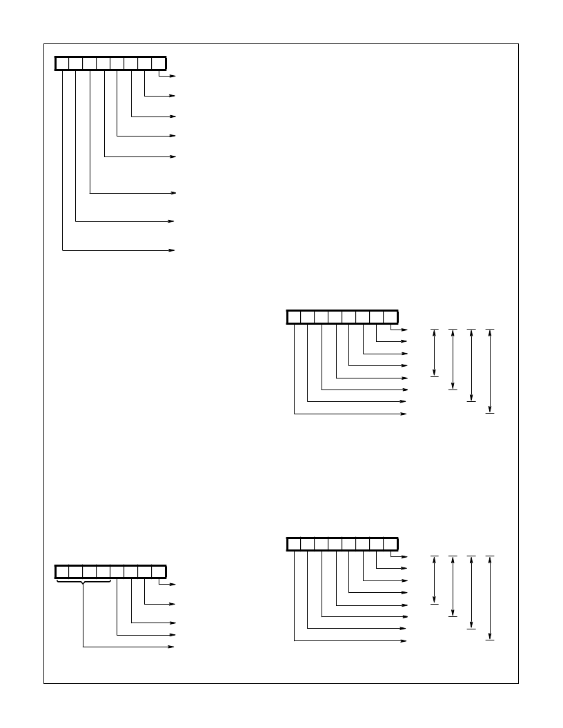
D7 D6 D5 D4 D3 D2 D1 D0
Parity Error
(PE)
0 = No Error
1 = Error
Framing Error
(FE)
0 = No Error
1 = Error
Overrun Error
(OE)
0 = No Error
1 = Error
Received
Break (RBRK)
0 = No Break
1 = Break
Modem Status
(MS)
0 = No Status
Change
1 = Status
Change
Transmission
Complete
(TC)
0 = Not
Complete
1 = Complete
Transmitter
Buffer Register
Empty (TBRE)
0 = Not Empty
1 = Empty
Data Ready
(DR)
0 = Not Ready
1 = Ready
FIGURE 5. USR
D7 D6 D5 D4 D3 D2 D1 D0
Clear to Send
(CTS)
0 = False
1 = Truer
Data Set
Ready (DSR)
0 = False
1 = True
0
0
Undefined
FIGURE 6. MSR
D7 D6 D5 D4 D3 D2 D1 D0
Bit 0
Bit 1
Bit 2
Bit 3
Bit 4
Bit 5
Bit 6
Bit 7
FIGURE 7. RBR
D7 D6 D5 D4 D3 D2 D1 D0
Bit 0
Bit 1
Bit 2
Bit 3
Bit 4
Bit 5
Bit 6
Bit 7
FIGURE 8. TBR
5-Bit
Word
6-Bit
Word
7-Bit
Word
8-Bit
Word
5-Bit
Word
6-Bit
Word
7-Bit
Word
8-Bit
Word
82C52
相关PDF资料 |
PDF描述 |
|---|---|
| IS82C54 | CMOS Programmable Interval Timer |
| IS82C54-10 | CMOS Programmable Interval Timer |
| IS82C54-12 | CMOS Programmable Interval Timer |
| IS82C82 | CMOS Octal Latching Bus Driver |
| IS82C83H | CMOS Octal Latching Inverting Bus Driver |
相关代理商/技术参数 |
参数描述 |
|---|---|
| IS82C52/TR100/BAE | 制造商:Intersil Corporation 功能描述:PERIPH UART/BRG 5V 16MHZ 28PLCC IND - Tape and Reel |
| IS82C5296 | 制造商:Rochester Electronics LLC 功能描述:- Bulk |
| IS82C52R2490 | 制造商:Rochester Electronics LLC 功能描述:- Bulk |
| IS82C52Z | 功能描述:UART 接口集成电路 W/ANNEAL PERIPH /BRG 5V 16MHZ RoHS:否 制造商:Texas Instruments 通道数量:2 数据速率:3 Mbps 电源电压-最大:3.6 V 电源电压-最小:2.7 V 电源电流:20 mA 最大工作温度:+ 85 C 最小工作温度:- 40 C 封装 / 箱体:LQFP-48 封装:Reel |
| IS82C52Z96 | 功能描述:UART 接口集成电路 W/ANNEAL PERIPH /BRG 5V 16MHZ RoHS:否 制造商:Texas Instruments 通道数量:2 数据速率:3 Mbps 电源电压-最大:3.6 V 电源电压-最小:2.7 V 电源电流:20 mA 最大工作温度:+ 85 C 最小工作温度:- 40 C 封装 / 箱体:LQFP-48 封装:Reel |
发布紧急采购,3分钟左右您将得到回复。