参数资料
| 型号: | ISL12022MAIBZ |
| 厂商: | Intersil |
| 文件页数: | 9/31页 |
| 文件大小: | 0K |
| 描述: | IC RTC/CALENDAR TEMP SNSR 20SOIC |
| 产品培训模块: | Solutions for Industrial Control Applications |
| 标准包装: | 38 |
| 类型: | 时钟/日历 |
| 特点: | 警报器,夏令时,闰年,SRAM |
| 存储容量: | 128B |
| 时间格式: | HH:MM:SS(12/24 小时) |
| 数据格式: | YY-MM-DD-dd |
| 接口: | I²C,2 线串口 |
| 电源电压: | 2.7 V ~ 5.5 V |
| 电压 - 电源,电池: | 1.8 V ~ 5.5 V |
| 工作温度: | -40°C ~ 85°C |
| 安装类型: | 表面贴装 |
| 封装/外壳: | 20-SOIC(0.295",7.50mm 宽) |
| 供应商设备封装: | 20-SOIC |
| 包装: | 管件 |
第1页第2页第3页第4页第5页第6页第7页第8页当前第9页第10页第11页第12页第13页第14页第15页第16页第17页第18页第19页第20页第21页第22页第23页第24页第25页第26页第27页第28页第29页第30页第31页
ISL12022MA
17
FN7575.5
September 5, 2012
register reaches 50h, then the LBAT75 bit will remain at “0” the
next time the device switches back to Normal Mode.
REAL TIME CLOCK FAIL BIT (RTCF)
This bit is set to a “1” after a total power failure. This is a read
only bit that is set by hardware (ISL12022MA internally) when
the device powers up after having lost all power (defined as VDD
= 0V and VBAT = 0V). The bit is set regardless of whether VDD or
VBAT is applied first. The loss of only one of the supplies does not
set the RTCF bit to “1”. The first valid write to the RTC section
after a complete power failure resets the RTCF bit to “0” (writing
one byte is sufficient).
Interrupt Control Register (INT)
AUTOMATIC RESET BIT (ARST)
This bit enables/disables the automatic reset of the ALM, LVDD,
LBAT85, and LBAT75 status bits only. When ARST bit is set to “1”,
these status bits are reset to “0” after a valid read of the
respective status register (with a valid STOP condition). When the
ARST is cleared to “0”, the user must manually reset the ALM,
LVDD, LBAT85, and LBAT75 bits.
WRITE RTC ENABLE BIT (WRTC)
The WRTC bit enables or disables write capability into the RTC
Timing Registers. The factory default setting of this bit is “0”.
Upon initialization or power-up, the WRTC must be set to “1” to
enable the RTC. Upon the completion of a valid write (STOP), the
RTC starts counting. The RTC internal 1Hz signal is synchronized
to the STOP condition during a valid write cycle.
INTERRUPT/ALARM MODE BIT (IM)
This bit enables/disables the interrupt mode of the alarm
function. When the IM bit is set to “1”, the alarm will operate in
the interrupt mode, where an active low pulse width of 250ms
will appear at the IRQ/FOUT pin when the RTC is triggered by the
alarm, as defined by the alarm registers (0Ch to 11h). When the
IM bit is cleared to “0”, the alarm will operate in standard mode,
where the IRQ/FOUT pin will be set low until the ALM status bit is
cleared to “0”.
FREQUENCY OUTPUT AND INTERRUPT BIT (FOBATB)
This bit enables/disables the IRQ/FOUT pin during battery
backup mode (i.e. VBAT power source active). When the FOBATB
is set to “1”, the IRQ/FOUT pin is disabled during battery backup
mode. This means that both the frequency output and alarm
output functions are disabled. When the FOBATB is cleared to
“0”, the IRQ/FOUT pin is enabled during battery backup mode.
Note that the open drain IRQ/FOUT pin will need a pull-up to the
battery voltage to operate in battery backup mode.
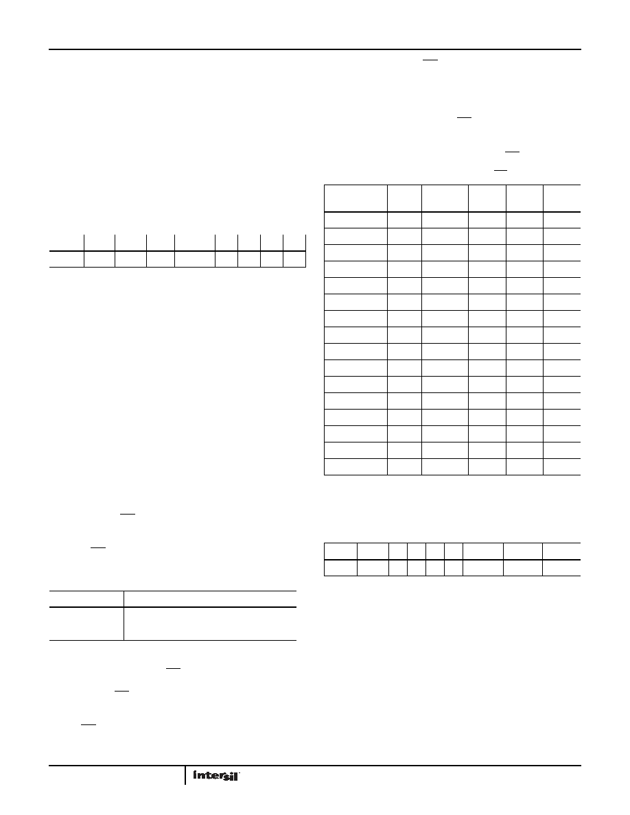
FREQUENCY OUT CONTROL BITS (FO <3:0>)
These bits enable/disable the frequency output function and
frequency selection. Default for the ISL12022MA is FO<3:0> = 1h,
or 32.768kHz output (FOUT is ON). When the frequency mode is
enabled, it will override the alarm mode at the IRQ/FOUT pin.
Power Supply Control Register (PWR_VDD)
CLEAR TIME STAMP BIT (CLRTS)
This bit clears Time Stamp VDD to Battery (TSV2B) and Time
Stamp Battery to VDD Registers (TSB2V). The default setting is 0
(CLRTS = 0) and the Enabled setting is 1 (CLRTS = 1).
VDD BROWNOUT TRIP VOLTAGE BITS (VDDTRIP<2:0>)
These bits set the trip level for the VDD alarm, indicating that VDD
has dropped below a preset level. In this event, the LVDD bit in
the Status Register is set to “1”. See Table 7.
TABLE 3. INTERRUPT CONTROL REGISTER (INT)
ADDR
7
6
5
4
321
0
08h
ARST
WRTC
IM
FOBATB
FO3 FO2 FO1 FO0
TABLE 4.
IM BIT
INTERRUPT/ALARM FREQUENCY
0
Single Time Event Set By Alarm
1
Repetitive/Recurring Time Event Set By Alarm
TABLE 5. FREQUENCY SELECTION OF IRQ/FOUT PIN
FREQUENCYFOU
T
UNITS
FO3
FO2
FO1
FO0
0Hz
0
32768
Hz
0
1
4096
Hz
0
1
0
1024
Hz
0
1
64
Hz
0
1
0
32
Hz
0
1
0
1
16
Hz
0
1
0
8Hz
0
1
4Hz
1
0
2Hz
1
0
1
1Hz
1
0
1
0
1/2
Hz
1
0
1
1/4
Hz
1
0
1/8
Hz
1
0
1
1/16
Hz
1
0
1/32
Hz
1
TABLE 6.
ADDR
7
6
5
4
3
2
1
0
09h
CLRTS
0
VDDTrip2 VDDTrip1 VDDTrip0
相关PDF资料 |
PDF描述 |
|---|---|
| ISL12022MIBZ-T7A | IC RTC/CALENDAR TEMP SNSR 20SOIC |
| ISL12022MIBZR5421 | IC RTC/CALENDAR TEMP SNSR 20SOIC |
| ISL12023IVZ | IC RTC/CLDR TEMP SNSR 14-TSSOP |
| ISL12024IRTCZ | IC RTC/CALENDER 64BIT 8-TDFN |
| ISL12024IVZ | IC RTC/CALENDAR EEPROM 8-TSSOP |
相关代理商/技术参数 |
参数描述 |
|---|---|
| ISL12022MAIBZ-T | 功能描述:实时时钟 REAL TIME CLK ENHANC CD ESD & MOISTURESIS RoHS:否 制造商:Microchip Technology 功能:Clock, Calendar. Alarm RTC 总线接口:I2C 日期格式:DW:DM:M:Y 时间格式:HH:MM:SS RTC 存储容量:64 B 电源电压-最大:5.5 V 电源电压-最小:1.8 V 最大工作温度:+ 85 C 最小工作温度: 安装风格:Through Hole 封装 / 箱体:PDIP-8 封装:Tube |
| ISL12022M-EVAL | 制造商:Intersil Corporation 功能描述:Low Power RTC with Battery Backed SRAM, Integrated 5ppm Temperature Compensation, and Auto Daylight Saving |
| ISL12022MIBZ | 功能描述:实时时钟 REAL TIME CLK & TEMP COMPENSATED CRYSTAL RoHS:否 制造商:Microchip Technology 功能:Clock, Calendar. Alarm RTC 总线接口:I2C 日期格式:DW:DM:M:Y 时间格式:HH:MM:SS RTC 存储容量:64 B 电源电压-最大:5.5 V 电源电压-最小:1.8 V 最大工作温度:+ 85 C 最小工作温度: 安装风格:Through Hole 封装 / 箱体:PDIP-8 封装:Tube |
| ISL12022MIBZ-EVAL | 功能描述:电源管理IC开发工具 ISL12022MIBZ-EVAL DEMO BRD RoHS:否 制造商:Maxim Integrated 产品:Evaluation Kits 类型:Battery Management 工具用于评估:MAX17710GB 输入电压: 输出电压:1.8 V |
| ISL12022MIBZR5421 | 功能描述:实时时钟 REAL TIME CLK W/MFK IMPROVED ESD AIR RoHS:否 制造商:Microchip Technology 功能:Clock, Calendar. Alarm RTC 总线接口:I2C 日期格式:DW:DM:M:Y 时间格式:HH:MM:SS RTC 存储容量:64 B 电源电压-最大:5.5 V 电源电压-最小:1.8 V 最大工作温度:+ 85 C 最小工作温度: 安装风格:Through Hole 封装 / 箱体:PDIP-8 封装:Tube |
发布紧急采购,3分钟左右您将得到回复。