参数资料
| 型号: | ISL12028IVAZ |
| 厂商: | Intersil |
| 文件页数: | 18/29页 |
| 文件大小: | 0K |
| 描述: | IC RTC/CALENDAR EEPROM 14-TSSOP |
| 产品培训模块: | Solutions for Industrial Control Applications |
| 标准包装: | 960 |
| 类型: | 时钟/日历 |
| 特点: | 警报器,闰年,监控器,监视计时器 |
| 时间格式: | HH:MM:SS(12/24 小时) |
| 数据格式: | YY-MM-DD-dd |
| 接口: | I²C,2 线串口 |
| 电源电压: | 2.7 V ~ 5.5 V |
| 电压 - 电源,电池: | 1.8 V ~ 5.5 V |
| 工作温度: | -40°C ~ 85°C |
| 安装类型: | 表面贴装 |
| 封装/外壳: | 14-TSSOP(0.173",4.40mm 宽) |
| 供应商设备封装: | 14-TSSOP |
| 包装: | 管件 |
第1页第2页第3页第4页第5页第6页第7页第8页第9页第10页第11页第12页第13页第14页第15页第16页第17页当前第18页第19页第20页第21页第22页第23页第24页第25页第26页第27页第28页第29页
25
FN8233.9
November 30, 2010
Backup Battery Operation
Many types of batteries can be used with the Intersil RTC
products. 3.0V or 3.6V Lithium batteries are appropriate, and
sizes are available that can power a Intersil RTC device for up
to 10 years. Another option is to use a supercapacitor for
applications where VDD may disappear intermittently for short
periods of time. Depending on the value of supercapacitor
used, backup time can last from a few days to two weeks (with
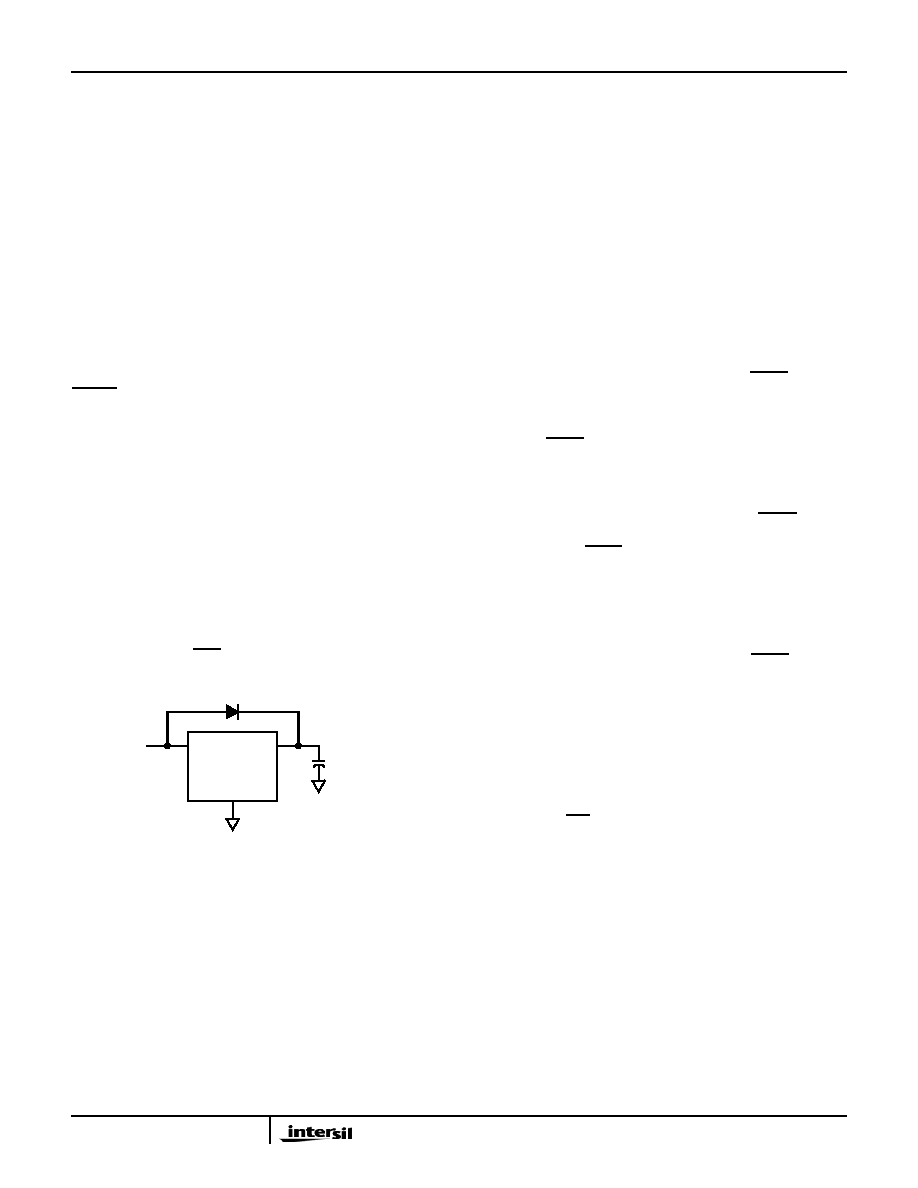
>1F). A simple silicon or Schottky barrier diode can be used in
series with VDD to charge the supercapacitor, which is
connected to the VBAT pin. Try to use Schottky diodes with
very low leakages, <1A desirable. Do not use the diode to
charge a battery (especially lithium batteries!).
Note that whether a battery or supercap is used, if the VBAT
voltage drops below the data sheet minimum of 1.8V and the
VDD power cycles to 0V then back to VDD voltage, then the
RESET output may stay low and the I2C communications will
not operate. The VBAT and VDD power will need to be cycled
to 0V together to allow normal operation again.
There are two possible modes for battery backup operation,
Standard and Legacy mode. In Standard mode, there are no
operational concerns when switching over to battery backup
since all other devices functions are disabled. Battery drain
is minimal in Standard mode, and return to Normal VDD
powered operations predictable. In Legacy modes the VBAT
pin can power the chip if the voltage is above VDD and
VTRIP. This makes it possible to generate alarms and
communicate with the device under battery backup, but the
supply current drain is much higher than the Standard mode
and backup time is reduced. In this case if alarms are used
in backup mode, the IRQ/FOUT pull up resistor must be
connected to VBAT voltage source..
I2C Communications During Battery Backup and
LVR Operation
Operation in Battery Backup mode and LVR is affected by
the BSW and SBIB bits as described earlier. These bits allow
flexible operation of the serial bus and EEPROM in battery
backup mode, but certain operational details need to be
clear before utilizing the different modes. The most
significant detail is that once VDD goes below VRESET, then
I2C communications cease regardless of whether the device
is programmed for I2C operation in battery backup mode.
Table 11 describes 4 different modes possible with using the
BSW and SBIB bits, and how they are affect LVR and battery
backup operation.
Mode A - In this mode, selection bits indicate a low VDD
switchover combined with I2C operation in battery backup
mode. In actuality the VDD will go below VRESET before
switching to battery backup, which will disable I2C
ANYTIME the device goes into battery backup mode.
Regardless of the battery voltage, the I2C will work down
Mode B - In this mode, the selection bits indicate
switchover to battery backup at VDD<VBAT, and I
2C
communications in battery backup. In order to
communicate in battery backup mode, the VRESET voltage
must be less than the VBAT voltage AND VDD must be
greater than VRESET. Also, pull-ups on the I
2C-bus pins
must go to VBAT to communicate. This mode is the same
as the normal operating mode of the X1228 device
Mode C - In this mode, the selection bits indicate a low
VDD switchover combined with no communications in
battery backup. Operation is actually identical to Mode A
with I2C communications down to VDD = VRESET, then no
communications (see Figure 29).
Mode D - In this mode, the selection bits indicate
switchover to battery backup at VDD<VBAT, and no I
2C
communications in battery backup. This mode is unique in
that there is I2C communication as long as VDD is higher
than VRESET or VBAT, whichever is greater. This mode is
the safest for guaranteeing I2C communications only when
Note that the IRQ/FOUT CMOS output pin is active in battery
backup for all modes. This should be considered if the load
on this pin is powered down, and could draw current from
the PMOS transistor and drain the battery. If that is the case,
the designer should consider the ISL12029 device which has
an open-drain output and avoids excessive current draw in
battery backup.
FIGURE 28. SUPERCAPACITOR CHARGING CIRCUIT
VDD
VBAT
VSS
SUPERCAPACITOR
2.7V TO 5.5V
ISL12028, ISL12028A
相关PDF资料 |
PDF描述 |
|---|---|
| AD5206BN10 | IC DGTL POT 6CH 256POS 24-DIP |
| VI-2NT-MW | CONVERTER MOD DC/DC 6.5V 100W |
| VE-B3F-MY-F3 | CONVERTER MOD DC/DC 72V 50W |
| AD5280BRUZ200 | IC DGTL POT 200K 256POS 14-TSSOP |
| VE-B3F-MY-F2 | CONVERTER MOD DC/DC 72V 50W |
相关代理商/技术参数 |
参数描述 |
|---|---|
| ISL12028IVAZ-T | 功能描述:实时时钟 REAL TIME CLKRTC W/ EPROM 4 64VSET 14 RoHS:否 制造商:Microchip Technology 功能:Clock, Calendar. Alarm RTC 总线接口:I2C 日期格式:DW:DM:M:Y 时间格式:HH:MM:SS RTC 存储容量:64 B 电源电压-最大:5.5 V 电源电压-最小:1.8 V 最大工作温度:+ 85 C 最小工作温度: 安装风格:Through Hole 封装 / 箱体:PDIP-8 封装:Tube |
| ISL12028IVZ | 功能描述:实时时钟 REAL TIME CLKRTC W/ EPROM IN 14LD RoHS:否 制造商:Microchip Technology 功能:Clock, Calendar. Alarm RTC 总线接口:I2C 日期格式:DW:DM:M:Y 时间格式:HH:MM:SS RTC 存储容量:64 B 电源电压-最大:5.5 V 电源电压-最小:1.8 V 最大工作温度:+ 85 C 最小工作温度: 安装风格:Through Hole 封装 / 箱体:PDIP-8 封装:Tube |
| ISL12028IVZ-T | 功能描述:实时时钟 REAL TIME CLKRTC W/ EPROM IN 14LD T RoHS:否 制造商:Microchip Technology 功能:Clock, Calendar. Alarm RTC 总线接口:I2C 日期格式:DW:DM:M:Y 时间格式:HH:MM:SS RTC 存储容量:64 B 电源电压-最大:5.5 V 电源电压-最小:1.8 V 最大工作温度:+ 85 C 最小工作温度: 安装风格:Through Hole 封装 / 箱体:PDIP-8 封装:Tube |
| ISL12029 | 制造商:INTERSIL 制造商全称:Intersil Corporation 功能描述:Real Time Clock/Calendar with I2C Bus? and EEPROM |
| ISL12029_10 | 制造商:INTERSIL 制造商全称:Intersil Corporation 功能描述:Real Time Clock/Calendar with I2C Busa?¢ and EEPROM |
发布紧急采购,3分钟左右您将得到回复。