参数资料
| 型号: | ISL1219IUZ-T |
| 厂商: | Intersil |
| 文件页数: | 16/24页 |
| 文件大小: | 0K |
| 描述: | IC RTC LP BATT BACK SRAM 10MSOP |
| 产品培训模块: | Solutions for Industrial Control Applications |
| 标准包装: | 2,500 |
| 类型: | 时间事件记录器 |
| 特点: | 警报器,闰年,SRAM |
| 存储容量: | 2B |
| 时间格式: | HH:MM:SS(12/24 小时) |
| 数据格式: | YY-MM-DD-dd |
| 接口: | I²C,2 线串口 |
| 电源电压: | 2.7 V ~ 5.5 V |
| 电压 - 电源,电池: | 1.8 V ~ 5.5 V |
| 工作温度: | -40°C ~ 85°C |
| 安装类型: | 表面贴装 |
| 封装/外壳: | 10-TFSOP,10-MSOP(0.118",3.00mm 宽) |
| 供应商设备封装: | 10-MSOP |
| 包装: | 带卷 (TR) |
23
FN6314.2
July 15, 2010
best choice. These devices are available from such vendors
as Panasonic and Murata. The main specifications include
working voltage and leakage current. If the application is for
charging the capacitor from a +5V ±5% supply with a signal
diode, then the voltage on the capacitor can vary from ~4.5V
to slightly over 5.0V. A capacitor with a rated WV of 5.0V
may have a reduced lifetime if the supply voltage is slightly
high. The leakage current should be as small as possible.
For example, a Super Capacitor should be specified with
leakage of well below 1A. A standard electrolytic capacitor
with DC leakage current in the microamps will have a
severely shortened backup time.
Below are some examples with equations to assist with
calculating backup times and required capacitance for the
ISL1219 device. The backup supply current plays a major
part in these equations, and a typical value was chosen for
example purposes. For a robust design, a margin of 30%
should be included to cover supply current and capacitance
tolerances over the results of the calculations. Even more
margin should be included if periods of very warm
temperature operation are expected.
Example 1. Calculating Backup Time Given
Voltages and Capacitor Value
5.0V, the voltage at VBAT will approach 4.7V as the diode turns
off completely. The ISL1219 is specified to operate down to
VBAT = 1.8V. The capacitance charge/discharge equation is
Rearranging gives
CBAT is the backup capacitance and dV is the change in
voltage from fully charged to loss of operation. Note that
ITOT is the total of the supply current of the ISL1219 (IBAT)
plus the leakage current of the capacitor and the diode, ILKG.
In these calculations, ILKG is assumed to be extremely small
and will be ignored. If an application requires extended
operation at temperatures over +50°C, these leakages will
increase and hence reduce backup time.
Note that IBAT changes with VBAT almost linearly (see
Typical Performance Curves). This allows us to make an
approximation of IBAT, using a value midway between the
two endpoints. The typical linear equation for IBAT vs. VBAT
is shown in Equation 4:
Using this equation to solve for the average current given 2
voltage points gives (Equation 5):
Combining with Equation 3 gives the equation for backup
time (Equation 6):
where:
CBAT = 0.47F
VBAT2 = 4.7V
VBAT1 = 1.8V
ILKG = 0 (assumed minimal)
TBACKUP = 0.47 * (2.9) / 4.38E-7 = 3.107E6 sec
Since there are 86,400 seconds in a day, this corresponds to
35.96 days. If the 30% tolerance is included for capacitor
and supply current tolerances, then worst case backup time
would be:
CBAT = 0.70 * 35.96 = 25.2 days
Example 2. Calculating a Capacitor Value for a
Given Backup Time
Referring to Figure 23 again, the capacitor value needs to be
calculated to give 2 months (60 days) of backup time, given
VDD = 5.0V. As in Example 1, the VBAT voltage will vary from
4.7V down to 1.8V. We will need to rearrange Equation 3 to
solve for capacitance (Equation 7):
Using the terms described above, this equation becomes
(Equation 8):
where:
TBACKUP = 60 days * 86,400 sec/day = 5.18 E6 sec
IBATAVG = 4.387 E-7 A (same as Example 1)
ILKG = 0 (assumed)
VBAT2 = 4.7V
VBAT1 = 1.8V
Solving gives:
CBAT = 5.18 E6 * (4.387 E-7)/(2.9) = 0.784F
If the 30% tolerance is included for tolerances, then worst
case cap value would be:
CBAT = 1.3 *.784 = 1.02F
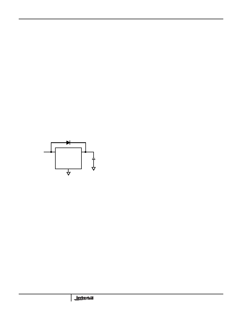
FIGURE 23. SUPERCAPACITOR CHARGING CIRCUIT
2.7V to 5.5V
VDD
VBAT
GND
1N4148
CBAT
I = CBAT * dV/dT
(EQ. 2)
dT = CBAT * dV/ITOT to solve for backup time.
(EQ. 3)
IBAT = 1.031E-7*(VBAT) + 1.036E-7 Amps
(EQ. 4)
IBATAVG = 5.155E-8*(VBAT2 + VBAT1) + 1.036E-7 Amps
(EQ. 5)
TBACKUP = CBAT * (VBAT2 - VBAT1) / (IBATAVG + ILKG)
(EQ. 6)
seconds
CBAT = dT*I/dV
(EQ. 7)
CBAT = TBACKUP * (IBATAVG + ILKG)/(VBAT2 – VBAT1)
(EQ. 8)
ISL1219
相关PDF资料 |
PDF描述 |
|---|---|
| ISL1220IUZ | IC RTC LP BATT BACK SRAM 10MSOP |
| ISL1221IUZ | IC RTC LP BATT BACK SRAM 10MSOP |
| ISL26134AVZ | IC ADC 24BIT SRL 80SPS 28TSSOP |
| ISL26319FVZ-T7A | IC ADC 12BIT SRL/SPI 16TSSOP |
| ISL26329FVZ | IC ADC 12BIT SPI/SRL 16-TSSOP |
相关代理商/技术参数 |
参数描述 |
|---|---|
| ISL1220 | 制造商:INTERSIL 制造商全称:Intersil Corporation 功能描述:I2C㈢ Real Time Clock/Calendar with Frequency Output |
| ISL1220IUZ | 功能描述:实时时钟 REAL TIME CLKRTC IN RoHS:否 制造商:Microchip Technology 功能:Clock, Calendar. Alarm RTC 总线接口:I2C 日期格式:DW:DM:M:Y 时间格式:HH:MM:SS RTC 存储容量:64 B 电源电压-最大:5.5 V 电源电压-最小:1.8 V 最大工作温度:+ 85 C 最小工作温度: 安装风格:Through Hole 封装 / 箱体:PDIP-8 封装:Tube |
| ISL1220IUZ-T | 功能描述:实时时钟 REAL TIME CLKRTC IN RoHS:否 制造商:Microchip Technology 功能:Clock, Calendar. Alarm RTC 总线接口:I2C 日期格式:DW:DM:M:Y 时间格式:HH:MM:SS RTC 存储容量:64 B 电源电压-最大:5.5 V 电源电压-最小:1.8 V 最大工作温度:+ 85 C 最小工作温度: 安装风格:Through Hole 封装 / 箱体:PDIP-8 封装:Tube |
| ISL1221 | 制造商:INTERSIL 制造商全称:Intersil Corporation 功能描述:Low Power RTC with Battery Backed |
| ISL1221IUZ | 功能描述:实时时钟 REAL TIME CLKRTC IN RoHS:否 制造商:Microchip Technology 功能:Clock, Calendar. Alarm RTC 总线接口:I2C 日期格式:DW:DM:M:Y 时间格式:HH:MM:SS RTC 存储容量:64 B 电源电压-最大:5.5 V 电源电压-最小:1.8 V 最大工作温度:+ 85 C 最小工作温度: 安装风格:Through Hole 封装 / 箱体:PDIP-8 封装:Tube |
发布紧急采购,3分钟左右您将得到回复。