- 您现在的位置:买卖IC网 > PDF目录383129 > ISL29003 (Intersil Corporation) Light-to-Digital Output Sensor with High Sensitivity, Gain Selection, Interrupt Function and I2C Interface(具有高灵敏度,增益可选,中断功能和I2C接口的光电输出传感器) PDF资料下载
参数资料
| 型号: | ISL29003 |
| 厂商: | Intersil Corporation |
| 英文描述: | Light-to-Digital Output Sensor with High Sensitivity, Gain Selection, Interrupt Function and I2C Interface(具有高灵敏度,增益可选,中断功能和I2C接口的光电输出传感器) |
| 中文描述: | 光到数字输出传感器灵敏度高,增益选择,中断功能和I2C接口(具有高灵敏度,增益可选,中断功能和的I2C接口的光电输出传感器) |
| 文件页数: | 8/15页 |
| 文件大小: | 258K |
| 代理商: | ISL29003 |
8
FN7464.3
October 8, 2007
COUNTER is the number increments accrued for between
integration time for External Timing Mode.
Gain/Range, Range(k)
The Gain/Range can be programmed in the control register
to give Range (k) determining the FSR. Note that Range(k)
is not the FSR. See Equation 3. Range(k) provides four
constants depending on programmed k that will be scaled by
R
EXT
. See Table 9. Unlike R
EXT
, Range(k) dynamically
adjusts the FSR. This function is especially useful when light
conditions are varying drastically while maintaining excellent
resolution.
Number of Clock Cycles, n-bit ADC
The number of clock cycles determines “n” in the n-bit ADC; 2
n
clock cycles is a n-bit ADC. n is programmable in the command
register in the width function. Depending on the application, a
good balance of speed, and resolution has to be considered
when deciding for n. For fast and quick measurement, choose
the smallest n = 4. For maximum resolution without regard of
time, choose n = 16. Table 12 compares the trade-off between
integration time and resolution. See Equations 10 and 11 for the
relation between integration time and n. See Equation 3 for the
relation of n and resolution.
External Scaling Resistor R
EXT
and f
osc
The ISL29003 uses an external resistor R
EXT
to fix its
internal oscillator frequency, f
OSC
. Consequently, R
EXT
determines the f
OSC
, integration time and the FSR of the
device. f
OSC
, a dual speed mode oscillator, is inversely
proportional to R
EXT
. For user simplicity, the proportionality
constant is referenced to fixed constants 100k
Ω
and
655kHz:
Ω
EXT
f
OSC
1 is oscillator frequency when Range1 or Range2 are
set. This is nominally 327kHz when R
EXT
is 100k
Ω
.
f
OSC
2 is the oscillator frequency when Range3 or Range4
are set. This is nominally 655kHz when R
EXT
is 100k
Ω
.
When the Range/Gain bits are set to Range1 or Range2,
f
OSC
runs at half speed compared to when Range/Gain bits
are set to Range3 and Range4.
The automatic f
OSC
adjustment feature allows significant
improvement of signal-to-noise ratio when detecting very low
lux signals.
Integration Time or Conversion Time
Integration time is the period during which the device’s
analog-to-digital ADC converter samples the photodiode
current signal for a lux measurement. Integration time, in
other words, is the time to complete the conversion of analog
photodiode current into a digital signal (number of counts).
Integration time affects the measurement resolution. For
better resolution, use a longer integration time. For short and
fast conversions use a shorter integration time.
The ISL29003 offers user flexibility in the integration time to
balance resolution, speed and noise rejection. Integration time
can be set internally or externally and can be programmed in
the command register 00(hex) bit 5.
INTEGRATION TIME IN INTERNAL TIMING MODE
This timing mode is programmed in the command register
00(hex) bit 5. Most applications will be using this timing
mode. When using the Internal Timing Mode, f
OSC
and
n-bits resolution determine the integration time. t
int
is a
function of the number of clock cycles and f
OSC
.
2
n
osc
n = 4, 8, 12, and16. n is the number of bits of resolution.
2
n
therefore is the number of clock cycles. n can be
programmed at the command register 00(hex) bits 1 and 0.
Since f
OSC
is dual speed depending on the Gain/Range bit,
t
int
is dual time. The integration time as a function of R
EXT
and n is:
R
Ω
t
int1
is the integration time when the device is configured
for Internal Timing Mode and Gain/Range is set to Range1
or Range2.
t
int2
is the integration time when the device is configured
for Internal Timing Mode and Gain/Range is set to Range3
or Range4.
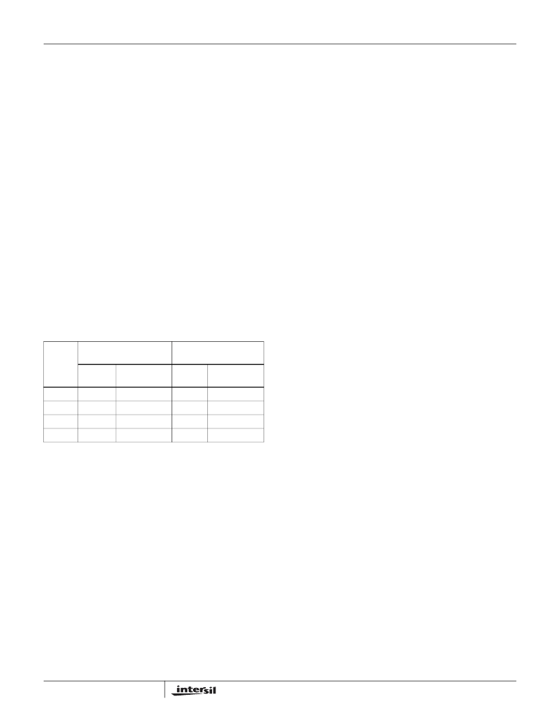
TABLE 12. RESOLUTION AND INTEGRATION TIME
SELECTION
n
RANGE1
f
OSC
= 327kHz
RESOLUTION
LUX/COUNT
RANGE4
f
OSC
= 655kHz
RESOLUTION
(LUX/COUNT)
t
INT
(ms)
200
t
INT
(ms)
100
16
0.01
1
12
12.8
0.24
6.4
16
8
0.8
3.90
0.4
250
4
0.05
62.5
0.025
4000
R
EXT
= 100k
Ω
(EQ. 6)
fosc1
1
2
--
-----------------
655
×
kHz
×
=
(EQ. 7)
fosc2
Ω
EXT
-----------------
655
×
kHz
=
(EQ. 8)
f
OSC
1
1
2
--
f
OSC
2
(
)
=
t
int
----------
×
=
(EQ. 9)
for Internal Timing Mode only
t
int
1
2
n
---------------------------------------------
×
=
(EQ. 10)
t
int
2
2
n
R
Ω
---------------------------------------------
×
=
(EQ. 11)
ISL29003
相关PDF资料 |
PDF描述 |
|---|---|
| ISL36356A-APDK-EVAL | PRISM 11Mbps Wireless Local Area Network Access Point |
| ISL36356A-APDK | PRISM 11Mbps Wireless Local Area Network Access Point |
| ISL3690IR-TK | Dual Band Direct Conversion Transceiver |
| ISL3690IR | Dual Band Direct Conversion Transceiver |
| ISL3690 | DIODE ZENER SINGLE 1000mW 7.5Vz 34mA-Izt 0.05 10uA-Ir 5Vr DO41-GLASS 5K/REEL |
相关代理商/技术参数 |
参数描述 |
|---|---|
| ISL29003IROZ | 功能描述:IC SENSOR LIGHT-DGTL I2C 6-ODFN RoHS:是 类别:传感器,转换器 >> 光学 - 光电探测器 - 环境光传感器 系列:- 产品培训模块:Lead (SnPb) Finish for COTS Obsolescence Mitigation Program 产品变化通告:Product Discontinuation 25/Jun/2012 标准包装:2,500 系列:- 带接近传感器:无 波长:- 电源电压:1.7 V ~ 2 V 电流 - 暗(标准):- 电流 - 光(典型值):- 输出类型:数字 - I²C 工作温度:-40°C ~ 85°C 安装类型:表面贴装 封装/外壳:6-UDFN 裸露焊盘 包装:带卷 (TR) |
| ISL29003IROZ-EVALZ | 功能描述:EVALUATION BOARD FOR ISL29003 RoHS:是 类别:编程器,开发系统 >> 评估板 - 传感器 系列:- 产品培训模块:Lead (SnPb) Finish for COTS Obsolescence Mitigation Program 标准包装:1 系列:- |
| ISL29003IROZ-T7 | 功能描述:光学数位转换器 ISL29003IROZ LIGHT-T O-DIGTL I2C GAIN RoHS:否 制造商:ams 数据总线宽度: 峰值波长:470 nm 最大工作频率: 工作电源电压: 工作电流: 最大工作温度:+ 85 C 最小工作温度:- 40 C 封装 / 箱体:Chipscale-6 封装:Reel |
| ISL29004IROZ | 功能描述:IC SENSOR LIGHT-DGTL I2C 8-ODFN RoHS:是 类别:传感器,转换器 >> 光学 - 光电探测器 - 环境光传感器 系列:- 产品培训模块:Lead (SnPb) Finish for COTS Obsolescence Mitigation Program 产品变化通告:Product Discontinuation 25/Jun/2012 标准包装:2,500 系列:- 带接近传感器:无 波长:- 电源电压:1.7 V ~ 2 V 电流 - 暗(标准):- 电流 - 光(典型值):- 输出类型:数字 - I²C 工作温度:-40°C ~ 85°C 安装类型:表面贴装 封装/外壳:6-UDFN 裸露焊盘 包装:带卷 (TR) |
| ISL29004IROZ-EVALZ | 制造商:Intersil Corporation 功能描述:INTRFC LIGHT-TO-DGTL OUTPUT SENSOR - Bulk |
发布紧急采购,3分钟左右您将得到回复。