参数资料
| 型号: | ISL5585GCR-TK |
| 厂商: | Intersil |
| 文件页数: | 13/24页 |
| 文件大小: | 0K |
| 描述: | IC SLIC RINGING 3.3V VOB 32-QFN |
| 标准包装: | 1,000 |
| 功能: | 用户线路接口概念(SLIC) |
| 电路数: | 1 |
| 电源电压: | 3.3V |
| 功率(瓦特): | 305mW |
| 工作温度: | 0°C ~ 85°C |
| 安装类型: | 表面贴装 |
| 封装/外壳: | 32-VQFN 裸露焊盘 |
| 供应商设备封装: | 32-QFN(7x7) |
| 包装: | 带卷 (TR) |
| 包括: | 均衡和不均衡振铃,振铃声信号发生器,热关机,带警报指示器 |
20
Power Denial
Overview
The power denial mode (111) will shutdown the entire device
except for the logic interface. Loop supervision is not
provided. This mode may be used as a sleep mode or to
shut down in the presence of a persistent thermal alarm.
Switching between high and low battery will have no effect
during power denial.
Functionality
During power denial, both the Tip and Ring amplifiers are
disabled, representing high impedances. The voltages at
both outputs are near ground.
Thermal Shutdown
In the event the safe die temperature is exceeded, the ALM
output will go low and DET will go high and the part will
automatically shut down. When the device cools, ALM will
go high and DET will reflect the loop status. If the thermal
fault persists, ALM will go low again and the part will shut
down. Programming power denial will permanently
shutdown the device and stop the self cooling cycling.
Battery Switching
Overview
The integrated battery switch selects between the high
battery and low battery. The battery switch is controlled
with the logic input BSEL. When BSEL is a logic high, the
high battery is selected and when a logic low, the low
battery is selected. All operating modes of the device will
operate from high or low battery except forward loop back,
which requires low battery for thermal reasons.
Functionality
The logic control is independent of the operating mode
decode. Independent logic control provides the most
flexibility and will support all application configurations.
When changing device operating states, battery switching
should occur simultaneously with or prior to changing the
operating mode. In most cases, this will minimize overall
power dissipation and prevent glitches on the DET output.
The only external component required to support the battery
switch is a diode in series with the VBH supply lead. In the
event that high battery is removed, the diode allows the
device to transition to low battery operation.
Low Battery Operation
All off hook operating conditions should use the low battery.
The prime benefit will be reduced power dissipation. The
typical low battery for the device is -24V. However this may
be increased to support longer loop lengths or high loop
current requirements. Standby conditions may also operate
from the low battery if MTU compliance is not required,
further reducing standby power dissipation.
High Battery Operation
Other than during ringing, the high battery should be used
for standby conditions which must provide MTU compliance.
During standby operation the power consumption is typically
85mW with -100V battery. If ringing requirements do not
require full 100V operation, then a lower battery will result in
lower standby power.
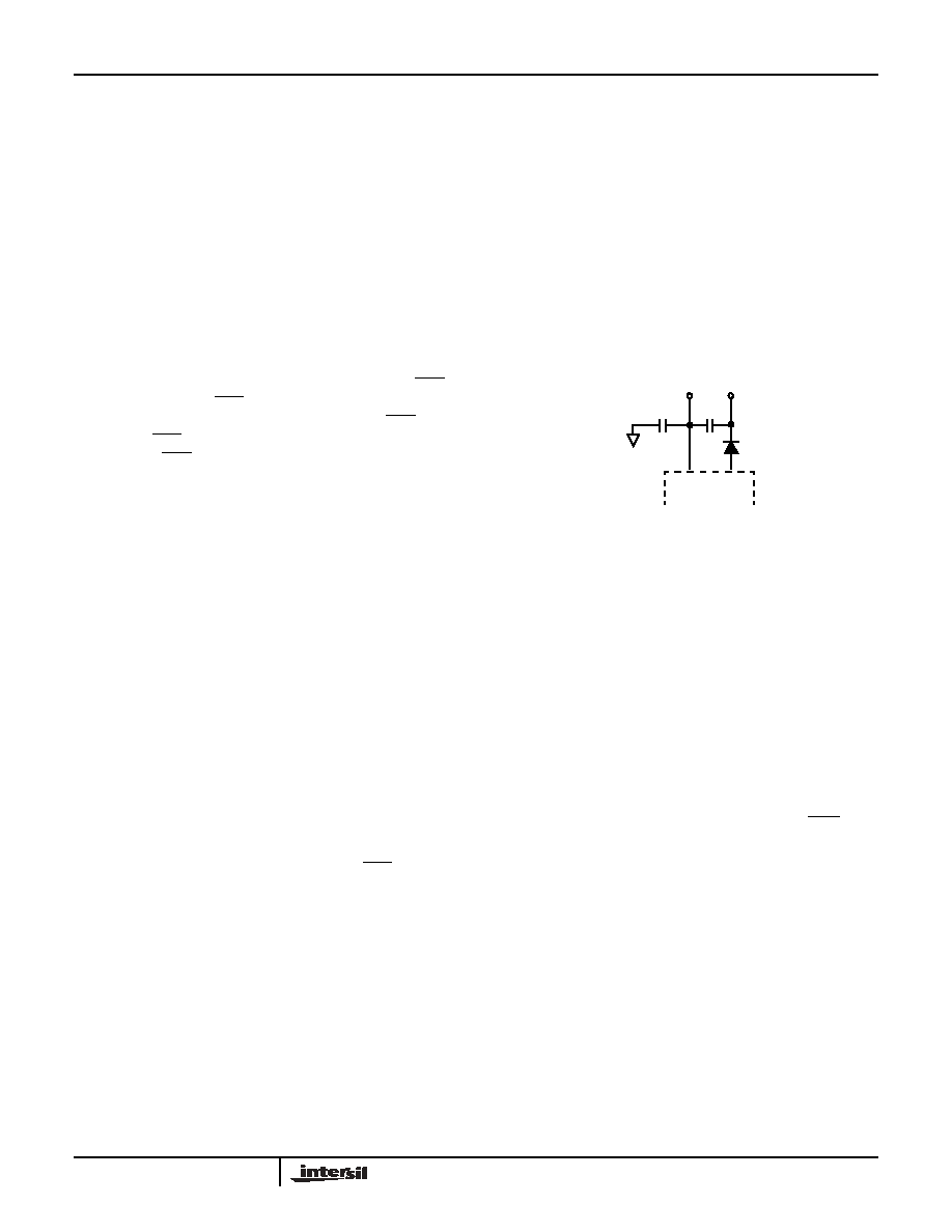
High Voltage Decoupling
The 100V rating of the device will require a capacitor of
higher voltage rating for decoupling. Suggested decoupling
values for all device pins are 0.1
F. Standard surface mount
ceramic capacitors are rated at 100V. For applications driven
at low cost and small size, the decoupling scheme shown
below could be implemented.
It is important to place the external diode between the VBH
pin and the decoupling capacitor. Attaching the decoupling
capacitor directly to the VBH pin will degrade the reliability of
the device. Refer to Figure 14 for the proper arrangement.
This applies to both single and stacked and decoupling
arrangements.
If VBL and VBH are tied together to override the battery
switch function, then the external diode is not needed and
the decoupling may be attached directly to VBH.
Uncommitted Switch
Overview
The uncommitted switch is a three terminal device designed
for flexibility. The independent logic control input, SWC,
allows switch operation regardless of device operating
mode. The switch is activated by a logic low. The positive
and negative terminals of the device are labeled SW+ and
SW- respectively.
Relay Driver
The uncommitted switch may be used as a relay driver by
connecting SW+ to the relay coil and SW- to ground. The
FIGURE 14. ALTERNATE DECOUPLING SCHEME
VBH
VBL
0.22
0.22
ISL5585
相关PDF资料 |
PDF描述 |
|---|---|
| ISL5586DIMZ | IC SLIC RINGING LP HOME 28-PLCC |
| ISL59450IQZ | IC SWITCH VID CRSSPNT 128-MQFP |
| ISL59530IRZ | IC VIDEO CROSSPOINT SWITCH 72QFN |
| ISL59532IKEZ | IC CROSSPOINT SW 32X32 356BGA |
| ISL59534IKEZ | IC CROSSPOINT SW 32X16 356BGA |
相关代理商/技术参数 |
参数描述 |
|---|---|
| ISL5585GCRZ | 制造商:Intersil Corporation 功能描述:PB-FREE RINGING SLIC W/3.3V VCC, 100V/53DB - Rail/Tube 制造商:Rochester Electronics LLC 功能描述: |
| ISL5585GCRZ-T | 制造商:Intersil Corporation 功能描述:PB-FREE RINGING SLIC W/3.3V VCC, 100V/53DB, T&R - Tape and Reel |
| ISL5585GCRZ-TK | 制造商:Intersil Corporation 功能描述:SLIC 1CH 53DB 45MA 3.3V/-18V/-24V/-28V 32QFN EP - Tape and Reel |
| ISL5585XEVAL1 | 功能描述:EVALUATION BOARD FOR ISL5585 RoHS:否 类别:编程器,开发系统 >> 过时/停产零件编号 系列:- 标准包装:1 系列:- 传感器类型:CMOS 成像,彩色(RGB) 传感范围:WVGA 接口:I²C 灵敏度:60 fps 电源电压:5.7 V ~ 6.3 V 嵌入式:否 已供物品:成像器板 已用 IC / 零件:KAC-00401 相关产品:4H2099-ND - SENSOR IMAGE WVGA COLOR 48-PQFP4H2094-ND - SENSOR IMAGE WVGA MONO 48-PQFP |
| ISL5586 | 制造商:INTERSIL 制造商全称:Intersil Corporation 功能描述:Low Power Ringing SLIC for Home Gateways |
发布紧急采购,3分钟左右您将得到回复。