- 您现在的位置:买卖IC网 > PDF目录383135 > ISL5586CIM (INTERSIL CORP) Low Power Ringing SLIC for Home Gateways PDF资料下载
参数资料
| 型号: | ISL5586CIM |
| 厂商: | INTERSIL CORP |
| 元件分类: | 模拟传输电路 |
| 英文描述: | Low Power Ringing SLIC for Home Gateways |
| 中文描述: | TELECOM-SLIC, PQCC28 |
| 封装: | PLASTIC, MS-018AB, LCC-28 |
| 文件页数: | 8/20页 |
| 文件大小: | 497K |
| 代理商: | ISL5586CIM |
4-8
To allow for proper ring trip operation, the transient current
limit setting should be set at least 25% higher than the peak
ring trip current setting. Setting the transient current 25%
higher should account for programming tolerances of both
the ring trip threshold and the transient current limit.
If loop current is larger than ring trip current (low REN
applications) then the transient current limit should be set at
least 35% higher than the loop current setting. The slightly
higher offset accounts for the slope of the loop current limit
function.
Attention to detail should be exercised when programming
the transient current limit setting. If ring trip detect does not
occur while ringing, then re-examine the transient current
limit and ring trip threshold settings.
Low Power Standby Mode
Overview
The low power standby mode (LPS, 000) should be used in
conjunction with the high battery during idle line conditions.
The SLIC is designed to operate from the high battery during
this mode so MTU compliance can be met. Most of the
internal circuitry is powered down, resulting in low power
dissipation. If MTU compliance is not required during idle line
conditions, the device may be operated from the low battery
which will decrease the standby power dissipation.
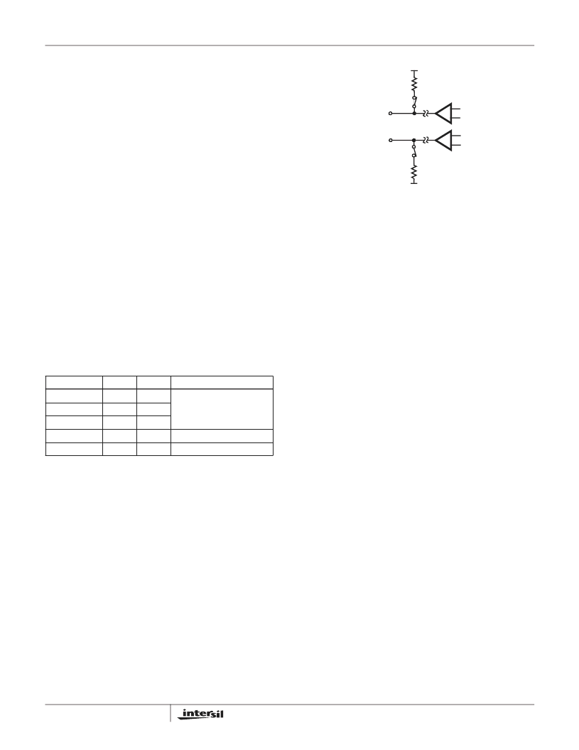
2-Wire Interface
In the LPS mode, the 2-wire interface is maintained with
internal switches, resistors, and voltage references. The Tip
and Ring amplifiers are turned off to conserve power. The
device will provide MTU compliance, loop current, and loop
supervision. Figure 2 represents the internal circuitry
providing the 2-wire interface when in this mode of operation.
MTU Compliance
Maintenance Termination Unit or MTU compliance places
DC voltage requirements on the 2-wire terminals during idle
line conditions. The minimum idle voltage for compliance is
42.75V. The high side of the MTU range is 56V. The voltage
is expressed as the difference between Tip and Ring.
The Tip voltage is held near ground through a 600
resistor
and switch. The Ring voltage is nominally limited to -49V by
the MTU reference. A switch and 600
resistor connect the
MTU reference to the Ring terminal. When the high battery
voltage exceeds the MTU reference of -49V, the Ring
terminal will be clamped by the internal reference. The same
Ring relationships apply when operating from the low
battery. For operating battery voltages (V
BH
) less than or
equal to the internal MTU reference, the Ring voltage will be
approximately 4.5 volts more positive than V
BH
.
Loop Current
In the LPS mode, the device is capable of providing DC
current to a load through a path of resistors and switches.
The current available for switch hook detect is a function of
the off hook loop resistance (R
LOOP
). This includes the off
hook phone resistance and copper loop resistance. The
current available during LPS is given by Equation 15.
Internal current limiting of the standby switches will limit the
maximum current to approximately 23mA. The longitudinal
current capability is guaranteed to be greater than or equal to
10mA
RMS
per pin. When longitudinal currents exceed this
level, false off hook detection may occur. The reduction in
longitudinalcurrentcapability with respect to the Forward Active
mode is a result of turning off the Tip and Ring amplifiers.
On Hook Power Dissipation
The on hook power dissipation of the SLIC in the LPS mode
is determined by the operating voltages and quiescent
currents and is calculated below.
TABLE 1. DEVICE INTERFACES DURING LPS
INTERFACE
ON
OFF
NOTES
Receive
-
x
ACtransmission, impedance
matching and ringing are
disabled during this mode.
Ringing
-
x
Transmit
-
x
2-Wire
x
-
Amplifiers disabled.
Loop Detect
x
-
Switch hook.
FIGURE 3. LPS 2-WIRE INTERFACE CIRCUIT DIAGRAM
TIP AMP
RING AMP
TIP
RING
MTU REF
GND
600
600
I
LOOP
1
–
49
–
(
)
–
(
)
600
600
R
LOOP
+
+
(
)
=
(EQ. 15)
P
LPS
V
BH
I
BHQ
×
V
BL
I
BLQ
×
V
CC
I
CCQ
×
+
+
=
(EQ. 16)
ISL5586
相关PDF资料 |
PDF描述 |
|---|---|
| ISL5586DIM | Low Power Ringing SLIC for Home Gateways |
| ISL56292IN | Dual 8-bit, +3.3V, 130/210MSPS, CommLink TM High Speed D/A Converter |
| ISL5629IN | Dual 8-bit, +3.3V, 130/210MSPS, CommLink TM High Speed D/A Converter |
| ISL5629EVAL1 | Dual 8-bit, +3.3V, 130/210MSPS, CommLink TM High Speed D/A Converter |
| ISL5629 | Dual 8-bit, +3.3V, 130/210+MSPS, High Speed D/A Converter(双路8位, +3.3V, 130/210+MSPS, 高速D/A转换器) |
相关代理商/技术参数 |
参数描述 |
|---|---|
| ISL5586DIM | 制造商:INTERSIL 制造商全称:Intersil Corporation 功能描述:Low Power Ringing SLIC for Home Gateways |
| ISL5586DIMZ | 功能描述:IC SLIC RINGING LP HOME 28-PLCC RoHS:是 类别:集成电路 (IC) >> 接口 - 电信 系列:RSLIC18 产品培训模块:Lead (SnPb) Finish for COTS 产品变化通告:Product Discontinuation 06/Feb/2012 标准包装:750 系列:* |
| ISL5586EVAL1 | 制造商:Intersil Corporation 功能描述:DEV TOOL, EVAL BD FOR LOW PWR RINGING SLIC FOR HOME GATEWAYS - Bulk |
| ISL5586FCM | 制造商:Rochester Electronics LLC 功能描述:RINGING SLIC FOR RESIDENTIAL HOME GATEWAYS 75V/53DB - Bulk 制造商:Intersil Corporation 功能描述: |
| ISL5586FCMT | 制造商:INTERSIL 功能描述:New |
发布紧急采购,3分钟左右您将得到回复。