参数资料
| 型号: | ISL6115AEVAL1Z |
| 厂商: | Intersil |
| 文件页数: | 6/10页 |
| 文件大小: | 0K |
| 描述: | EVAL BOARD 1 FOR ISL6115A |
| 标准包装: | 1 |
| 系列: | * |
�� �
�
�ISL6115A�
�Upon� a� UV� condition,� the� PGOOD� signal� will� pull� low�
�when� connected� through� a� resistor� to� the� logic� or� VDD�
�supply.� This� pin� is� a� UV� fault� indicator.� For� an� OC�
�latch-off� indication,� monitor� CTIM,� pin� 6.� This� pin� will�
�rise� rapidly� from� 1.8V� to� VDD� once� the� time-out� period�
�expires.�
�See� Figures� 2� through� 13� for� graphs� and� waveforms�
�related� to� text.�
�The� IC� is� reset� after� an� OC� latch-off� condition� by� a� low�
�level� on� the� PWRON� pin� and� is� turned� on� by� the�
�PWRON� pin� being� driven� high.�
�When� driving� particularly� large� capacitive� loads� a�
�longer� soft-start� time� to� prevent� current� regulation�
�upon� charging� and� a� short� CR� time� may� offer� the� best�
�application� solution� relative� to� reliability� and� FET� MTF.�
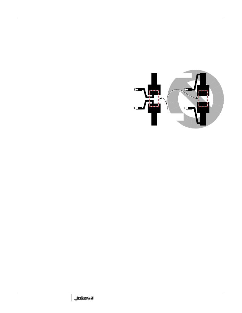
�Physical� layout� of� R� SENSE� resistor� is� critical� to�
�avoid� the� possibility� of� false� overcurrent� occurrences.�
�Ideally,� trace� routing� between� the� R� SENSE� resistors�
�and� the� IC� is� as� direct� and� as� short� as� possible� with�
�zero� current� in� the� sense� lines� (see� Figure� 1).�
�Application� Considerations�
�Design� applications� where� the� CR� Vth� is� set� extremely�
�low� (25mV� or� less),� there� is� a� two-fold� risk� to�
�consider.�
�?� There� is� the� susceptibility� to� noise� influencing� the�
�absolute� CR� Vth� value.� This� can� be� addressed� with� a�
�100pF� capacitor� across� the� R� SENSE� resistor.�
�?� Due� to� common� mode� limitations� of� the�
�overcurrent� comparator,� the� voltage� on� the� ISET�
�pin� must� be� 20mV� above� the� IC� ground� either�
�CORRECT�
�TO� ISEN� AND�
�R� ISET�
�INCORRECT�
�CURRENT�
�SENSE RESISTOR�
�initially� (from� I� SET� *R� SET� )� or� before� C� TIM� reaches�
�time-out� (from� gate� charge-up).� If� this� does� not�
�happen,� the� IC� may� incorrectly� report� overcurrent�
�fault� at� start-up� when� there� is� no� fault.� Circuits�
�with� high� load� capacitance� and� initially� low� load�
�current� are� susceptible� to� this� type� of� unexpected�
�behavior.�
�Do� not� signal� nor� pull-up� the� PWRON� input� to� >� 5V.�
�Exceeding� 6V� on� this� pin� will� cause� the� internal� charge�
�pump� to� malfunction.�
�During� the� soft-start� and� the� time-out� delay� duration�
�with� the� IC� in� its� current� limit� mode,� the� V� GS� of� the�
�external� N-Channel� MOSFET� is� reduced� driving� the�
�MOSFET� switch� into� a� (linear� region)� high� r� DS(ON)�
�state.� Strike� a� balance� between� the� CR� limit� and� the�
�timing� requirements� to� avoid� periods� when� the�
�external� N-Channel� MOSFETs� may� be� damaged� or�
�destroyed� due� to� excessive� internal� power� dissipation.�
�Refer� to� the� MOSFET� SOA� information� in� the�
�manufacturer’s� data� sheet.�
�6�
�.�
�FIGURE� 1.� SENSE� RESISTOR� PCB� LAYOUT�
�FN6855.1�
�April� 23,� 2010�
�相关PDF资料 |
PDF描述 |
|---|---|
| ISL6115EVAL1Z | EVAL BOARD ISL6115 |
| ISL6115EVAL1 | EVALUATION BOARD 12V ISL6115 |
| ISL6119USBEVAL1 | EVALUATION BOARD FOR ISL6119 |
| ISL6121EVAL1 | EVALUATION BOARD ISL6121 |
| ISL612XSEQEVAL1Z | EVALUATION BOARD ISL612XSEQ |
相关代理商/技术参数 |
参数描述 |
|---|---|
| ISL6115AIBZ | 功能描述:热插拔功率分布 W/ANNEAL 8LD+12V SNG HOT PLUG CONTRLR RoHS:否 制造商:Texas Instruments 产品:Controllers & Switches 电流限制: 电源电压-最大:7 V 电源电压-最小:- 0.3 V 工作温度范围: 功率耗散: 安装风格:SMD/SMT 封装 / 箱体:MSOP-8 封装:Tube |
| ISL6115AIBZ-T | 功能描述:热插拔功率分布 W/ANNEAL 8LD +12V HOT PLUG CNTRLR RoHS:否 制造商:Texas Instruments 产品:Controllers & Switches 电流限制: 电源电压-最大:7 V 电源电压-最小:- 0.3 V 工作温度范围: 功率耗散: 安装风格:SMD/SMT 封装 / 箱体:MSOP-8 封装:Tube |
| ISL6115AIBZ-T7A | 功能描述:热插拔功率分布 Pb-Free w/Anneal 8 LD SOIC, +12V SINGLE HOT PLUG CONTROLLER, RoHS:否 制造商:Texas Instruments 产品:Controllers & Switches 电流限制: 电源电压-最大:7 V 电源电压-最小:- 0.3 V 工作温度范围: 功率耗散: 安装风格:SMD/SMT 封装 / 箱体:MSOP-8 封装:Tube |
| ISL6115CB | 功能描述:IC MANAGER POWER HOT SWAP 8-SOIC RoHS:否 类别:集成电路 (IC) >> PMIC - 热交换 系列:- 产品培训模块:Obsolescence Mitigation Program 标准包装:100 系列:- 类型:热插拔开关 应用:通用 内部开关:是 电流限制:可调 电源电压:9 V ~ 13.2 V 工作温度:-40°C ~ 150°C 安装类型:表面贴装 封装/外壳:10-WFDFN 裸露焊盘 供应商设备封装:10-TDFN-EP(3x3) 包装:管件 |
| ISL6115CB-T | 功能描述:IC CTRLR POWER DISTRIB 8-SOIC RoHS:否 类别:集成电路 (IC) >> PMIC - 热交换 系列:- 产品培训模块:Obsolescence Mitigation Program 标准包装:100 系列:- 类型:热插拔开关 应用:通用 内部开关:是 电流限制:可调 电源电压:9 V ~ 13.2 V 工作温度:-40°C ~ 150°C 安装类型:表面贴装 封装/外壳:10-WFDFN 裸露焊盘 供应商设备封装:10-TDFN-EP(3x3) 包装:管件 |
发布紧急采购,3分钟左右您将得到回复。