参数资料
| 型号: | ISL6260CCRZ |
| 厂商: | Intersil |
| 文件页数: | 23/28页 |
| 文件大小: | 0K |
| 描述: | IC REG PWM MULTI-PHASE 40-QFN |
| 标准包装: | 50 |
| 应用: | 转换器,Intel IMVP-6 |
| 输出数: | 1 |
| 输出电压: | 0.3 V ~ 1.5 V |
| 工作温度: | -10°C ~ 100°C |
| 安装类型: | 表面贴装 |
| 封装/外壳: | 40-VFQFN 裸露焊盘 |
| 供应商设备封装: | 40-QFN(6x6) |
| 包装: | 管件 |
第1页第2页第3页第4页第5页第6页第7页第8页第9页第10页第11页第12页第13页第14页第15页第16页第17页第18页第19页第20页第21页第22页当前第23页第24页第25页第26页第27页第28页
�� �
�
�ISL6260C�
�IS� E� N� 1�
�IS� E� N� 2�
�IS� E� N� 3�
�I� p� h� a� s� e� 1�
�L� 1�
�+�
�V� d� cr� 1�
�-�
�IS� E� N� 1�
�OC�
�1� -�
�1� -�
�D� FB�
�C� L1�
�V� d� cr� 3�
�IS� E� N� 2�
�10uA�
�-�
�+�
�In� te� rn� a� l� to�
�IS� L� 6� 2� 6� 0�
�+�
�+�
�Σ�
�+� +�
�RTN�
�V� D� IF� F�
�0� .2� 2� u� F�
�IS� E� N� 3�
�OCSET�
�VSUM�
�+�
�DROOP�
�-�
�DROOP�
�VSEN�
�VO'�
�0� .0� 1� u� F�
�10�
�R� OCSET�
�VO'�
�VSUM�
�VO'�
�VSUM�
�VSUM�
�VSUM�
�RS1�
�I� p� h� a� s� e� 2�
�RS2�
�I� p� h� a� s� e� 3�
�RS3�
�R� L1�
�IS� E� N� 1�
�L� 2�
�R� L2�
�IS� E� N� 2�
�L� 3�
�R� L3�
�IS� E� N� 3�
�DCR�
�RO1�
�VO'�
�DCR�
�+� V� d� c� r� 2� -�
�RO2�
�C� L2�
�VO'�
�+� -�
�DCR�
�RO3�
�C� L3�
�Vout�
�C� b� u� lk�
�R� opn1�
�VCC_SENSE�
�to� V� o� u� t�
�T� o� P� ro� c� e� s� s� o� r�
�VO'�
�ESR�
�Ropn2�
�VSS_SENSE�
�S� o� c� k� e� t� K� e� lvin�
�C� o� n� n� e� c� tio� n� s�
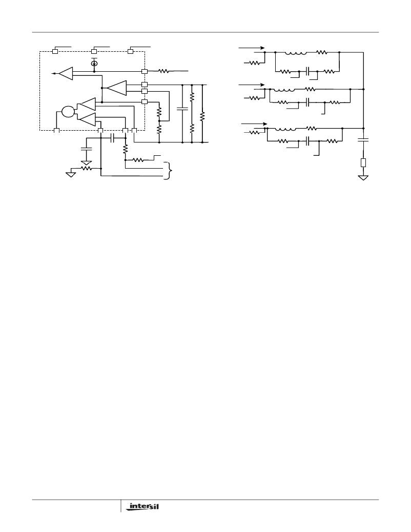
�FIGURE� 46.� EQUIVALENT� MODEL� FOR� DROOP� AND� DIE� SENSING� USING� DCR� SENSING�
�I� OUT� � DCR�
�Vdcr� EQV� =� ----------------------------------�
�Static� Mode� of� Operation� -� Static� Droop� using� DCR�
�Sensing�
�As� previously� mentioned,� the� ISL6260C� has� an� internal�
�differential� amplifier� which� provides� for� extremely� accurate�
�voltage� regulation� at� the� die� of� the� processor.� The� load� line�
�regulation� is� also� very� accurate,� and� the� process� of� selecting�
�the� components� for� the� appropriate� load� line� droop� is�
�explained� here.�
�For� DCR� sensing,� the� process� of� compensation� for� DCR�
�resistance� variation� to� achieve� the� desired� load� line� droop�
�has� several� steps� and� is� somewhat� iterative.�
�In� Figure� 46� we� show� a� 3� phase� solution� using� DCR�
�sensing.� There� are� two� resistors� around� the� inductor� of� each�
�phase.� These� are� labeled� RS� and� RO.� These� resistors� are�
�used� to� sense� the� DC� voltage� drop� across� each� inductor.�
�Each� inductor� will� have� a� certain� level� of� DC� current� flowing�
�through� it,� this� current� when� multiplied� by� the� DCR� of� the�
�inductor� creates� a� small� DC� level� of� voltage.� When� this�
�voltage� is� summed� with� the� other� channels� DC� voltages,� the�
�total� DC� load� current� can� be� derived.�
�RO� is� typically� 5� Ω� to� 10� Ω� .� This� resistor� is� used� to� tie� the�
�outputs� of� all� channels� together� and� thus� create� a� summed�
�average� of� the� local� CORE� voltage� output.� RS� is� determined�
�through� an� understanding� of� both� the� DC� and� transient� load�
�phase� and� one� RS� resistor� can� replace� the� RS� resistors� of�
�each� phase.� The� total� DCR� drop� due� to� load� current� can� be�
�replaced� by� a� DC� source,� the� value� of� which� is� given� by�
�Equation� 8.�
�(EQ.� 8)�
�N�
�where� N� is� the� number� of� channels� designed� for� active�
�operation.� Another� simplification� was� done� by� reducing� the�
�NTC� network� comprised� of� Rntc,� Rseries� and� Rparallel,�
�given� in� Figure� 46,� to� a� single� resistor� given� as� Rn� as� shown�
�in� Figure� 47.�
�The� first� step� in� droop� load� line� compensation� is� to� adjust�
�Rn,� RO� EQV� and� RS� EQV� such� that� sufficient� droop� voltage�
�exists� even� at� light� loads� between� the� VSUM� and� VO’� nodes.�
�We� recognize� that� these� components� form� a� voltage� divider.�
�As� a� rule� of� thumb� we� start� with� the� voltage� drop� across� the�
�Rn� network,� VN,� to� be� 0.57� x� Vdcr.� This� ratio� provides� for� a�
�fairly� reasonable� amount� of� light� load� signal� from� which� to�
�arrive� at� droop.�
�First� we� calculate� the� equivalent� NTC� network� resistance,�
�Rn.� Typical� values� that� provide� good� performance� are,�
�Rseries� =� 3.57k_1%,� Rpar� =� 4.53k_1%� and� Rntc� =� 10k� Ω�
�NTC,� ERT-J1VR103J� from� Panasonic.� Rn� is� then� given� by�
�Equation� 9.�
�(� --------------------------------------------------------------------�
�Rn� =� =� 3.4k� Ω�
�currents.� This� value� will� be� covered� in� the� next� section.�
�However,� it� is� important� to� keep� in� mind� that� the� output� of�
�Rseries� +� Rntc� )� � Rpar�
�Rseries� +� Rntc� +� Rpar�
�(EQ.� 9)�
�each� of� these� RS� resistors� are� tied� together� to� create� the�
�VSUM� voltage� node.� With� both� the� outputs� of� RO� and� RS�
�tied� together,� the� simplified� model� for� the� droop� circuit� can�
�be� derived.� This� is� presented� in� Figure� 47.�
�Figure� 47� shows� the� simplified� model� of� the� droop� circuitry.�
�Essentially� one� resistor� can� replace� the� RO� resistors� of� each�
�23�
�In� our� second� step� we� calculate� the� series� resistance� from�
�each� phase� to� the� Vsum� node,� labeled� RS1,� RS2� and� RS3�
�in� Figure� 46.�
�FN9259.3�
�June� 21,� 2010�
�相关PDF资料 |
PDF描述 |
|---|---|
| ISL6262AIRZ | IC CORE CTRLR 2PHASE 48-QFN |
| ISL6262IRZ | IC CORE CTRLR 2PHASE 48-QFN |
| ISL6263AIRZ | IC PWN CTRLR SYNC BUCK 32QFN |
| ISL6263BHRZ | IC DC/DC BUCK CTRLR 1PH 32-QFN |
| ISL6263CHRZ-T | IC VOLT REG 1PH 5BIT VID 32-QFN |
相关代理商/技术参数 |
参数描述 |
|---|---|
| ISL6260CCRZ-T | 功能描述:电流型 PWM 控制器 MULTI-PHS(3 PHS EXT DC/DC BUCK CONT RoHS:否 制造商:Texas Instruments 开关频率:27 KHz 上升时间: 下降时间: 工作电源电压:6 V to 15 V 工作电源电流:1.5 mA 输出端数量:1 最大工作温度:+ 105 C 安装风格:SMD/SMT 封装 / 箱体:TSSOP-14 |
| ISL6260CIRZ | 功能描述:电流型 PWM 控制器 MULTI-PHS(3 PHS EXT DC/DC BUCK CONT RoHS:否 制造商:Texas Instruments 开关频率:27 KHz 上升时间: 下降时间: 工作电源电压:6 V to 15 V 工作电源电流:1.5 mA 输出端数量:1 最大工作温度:+ 105 C 安装风格:SMD/SMT 封装 / 箱体:TSSOP-14 |
| ISL6260CIRZ-T | 功能描述:电流型 PWM 控制器 MULTI-PHS(3 PHS EXT DC/DC BUCK CONT RoHS:否 制造商:Texas Instruments 开关频率:27 KHz 上升时间: 下降时间: 工作电源电压:6 V to 15 V 工作电源电流:1.5 mA 输出端数量:1 最大工作温度:+ 105 C 安装风格:SMD/SMT 封装 / 箱体:TSSOP-14 |
| ISL6260CRZ | 功能描述:直流/直流开关调节器 MULTI-PHS3 PHS EXT DC/DC BUCK CNTRLR RoHS:否 制造商:International Rectifier 最大输入电压:21 V 开关频率:1.5 MHz 输出电压:0.5 V to 0.86 V 输出电流:4 A 输出端数量: 最大工作温度: 安装风格:SMD/SMT 封装 / 箱体:PQFN 4 x 5 |
| ISL6260CRZR5242 | 制造商:Intersil Corporation 功能描述:53289C01 MASK ONLY WITH DOT ON BRAND - Rail/Tube |
发布紧急采购,3分钟左右您将得到回复。