参数资料
| 型号: | ISL6262CRZ-T |
| 厂商: | Intersil |
| 文件页数: | 22/27页 |
| 文件大小: | 0K |
| 描述: | IC CORE REG 2PHASE 48-QFN |
| 标准包装: | 4,000 |
| 应用: | 转换器,Intel IMVP-6 |
| 输入电压: | 5 V ~ 25 V |
| 输出数: | 1 |
| 输出电压: | 0.3 V ~ 1.5 V |
| 工作温度: | -10°C ~ 100°C |
| 安装类型: | 表面贴装 |
| 封装/外壳: | 48-VFQFN 裸露焊盘 |
| 供应商设备封装: | 48-QFN(7x7) |
| 包装: | 带卷 (TR) |
第1页第2页第3页第4页第5页第6页第7页第8页第9页第10页第11页第12页第13页第14页第15页第16页第17页第18页第19页第20页第21页当前第22页第23页第24页第25页第26页第27页
�� �
�
�ISL6262�
�whether� Equation� 9� or� Equation� 10� can� accurately� represent�
�the� NTC� resistor� value� at� the� designed� temperature� range.�
�Therefore,� the� NTC� branch� is� designed� to� have� a� 470k� NTC�
�and� 4.02k� resistor� in� series.� The� part� number� of� the� NTC�
�thermistor� is� ERTJ0EV474J.� It� is� a� 0402� package.� The� NTC�
�thermistor� should� be� placed� in� the� spot� which� gives� the� best�
�indication� of� the� temperature� of� voltage� regulator� circuit.� The�
�actual� hysteresis� temperature� is� about� 105°C� and� 97°C.�
�Static� Mode� of� Operation� -� Static� Droop� Using� DCR�
�Sensing�
�As� previously� mentioned,� the� ISL6262� has� an� internal�
�through� an� understanding� of� both� the� DC� and� transient� load�
�currents.� This� value� will� be� covered� in� the� next� section.�
�However,� it� is� important� to� keep� in� mind� that� the� output� of�
�each� of� these� RS� resistors� are� tied� together� to� create� the�
�VSUM� voltage� node.� With� both� the� outputs� of� RO� and� RS�
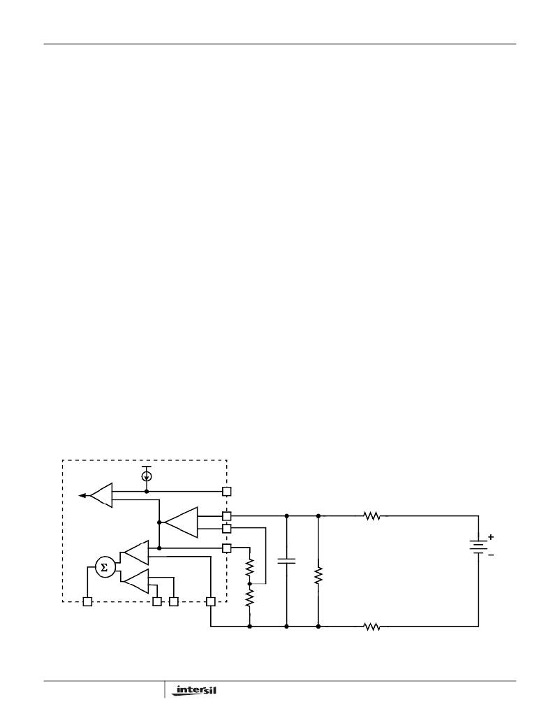
�tied� together,� the� simplified� model� for� the� droop� circuit� can�
�be� derived.� This� is� presented� in� Figure� 34.�
�Figure� 34� shows� the� simplified� model� of� the� droop� circuitry.�
�Essentially� one� resistor� can� replace� the� RO� resistors� of� each�
�phase� and� one� RS� resistor� can� replace� the� RS� resistors� of�
�each� phase.� The� total� DCR� drop� due� to� load� current� can� be�
�replaced� by� a� DC� source,� the� value� of� which� is� given� by:�
�V� DCR_EQU� =� ---------------------------------�
�differential� amplifier� which� provides� for� very� accurate� voltage�
�regulation� at� the� die� of� the� processor.� The� load� line�
�regulation� is� also� accurate� for� both� two-phase� and� single-�
�I� OUT� ?� DCR�
�2�
�(EQ.� 14)�
�phase� operation.� The� process� of� selecting� the� components�
�for� the� appropriate� load� line� droop� is� explained� here.�
�For� DCR� sensing,� the� process� of� compensation� for� DCR�
�resistance� variation� to� achieve� the� desired� load� line� droop�
�has� several� steps� and� is� somewhat� iterative.�
�The� two-phase� solution� using� DCR� sensing� is� shown� in�
�Figure� 31.� There� are� two� resistors� connecting� to� the�
�terminals� of� inductor� of� each� phase.� These� are� labeled� RS�
�and� RO.� These� resistors� are� used� to� obtain� the� DC� voltage�
�drop� across� each� inductor.� Each� inductor� will� have� a� certain�
�level� of� DC� current� flowing� through� it,� and� this� current� when�
�multiplied� by� the� DCR� of� the� inductor� creates� a� small� DC�
�For� the� convenience� of� analysis,� the� NTC� network�
�comprised� of� Rntc,� Rseries� and� Rpar,� given� in� Figure� 31,� is�
�labelled� as� a� single� resistor� Rn� in� Figure� 34.�
�The� first� step� in� droop� load� line� compensation� is� to� adjust�
�Rn,� RO� EQV� and� RS� EQV� such� that� sufficient� droop� voltage�
�exists� even� at� light� loads� between� the� VSUM� and� VO'� nodes.�
�As� a� rule� of� thumb� we� start� with� the� voltage� drop� across� the�
�Rn� network,� VN,� to� be� 0.5-0.8� times� V� DCR_EQU� .� This� ratio�
�provides� for� a� fairly� reasonable� amount� of� light� load� signal�
�from� which� to� arrive� at� droop.�
�The� resultant� NTC� network� resistor� value� is� dependent� on�
�the� temperature� and� given� by�
�R� n� (� T� )� =� --------------------------------------------------------------�
�voltage� drop� across� the� inductor� terminal.� When� this� voltage�
�is� summed� with� the� other� channels� DC� voltages,� the� total� DC�
�load� current� can� be� derived.�
�(� R� series� +� R� ntc� )� ?� R� par�
�R� series� +� R� ntc� +� R� par�
�(EQ.� 15)�
�RO� is� typically� 1� to� 10� Ω� .� This� resistor� is� used� to� tie� the�
�outputs� of� all� channels� together� and� thus� create� a� summed�
�average� of� the� local� CORE� voltage� output.� RS� is� determined�
�For� simplicity,� the� gain� of� Vn� to� the� V� dcr_equ� is� defined� by�
�G1,� also� dependent� on� the� temperature� of� the� NTC�
�thermistor.�
�10μA�
�OCSET�
�RS� EQV� =� --------�
�OC�
�-�
�+�
�INTERNAL� TO�
�+�
�DROOP�
�-�
�VSUM�
�DFB�
�VSUM�
�RS�
�2�
�Vdcr� EQV� =� I� OUT� � -------------�
�(� Rntc� +� Rseries� )� � Rpar�
�(� Rntc� +� Rseries� )� +� Rpar�
�ISL6262�
�VDIFF�
�+�
�+�
�+�
�1� -�
�+�
�1� -�
�RTN� VSEN�
�DROOP�
�VO'�
�Cn�
�+�
�VN�
�-�
�Rn� =� --------------------------------------------------------------------�
�DCR�
�2�
�RO� EQV� =� ---------�
�VO'�
�RO�
�2�
�FIGURE� 34.� EQUIVALENT� MODEL� FOR� DROOP� AND� DIE� SENSING� USING� DCR� SENSING�
�22�
�FN9199.2�
�May� 15,� 2006�
�相关PDF资料 |
PDF描述 |
|---|---|
| X40030S14I-CT1 | IC VOLTAGE MONITOR TRPL 14-SOIC |
| ASC25DREN-S13 | CONN EDGECARD 50POS .100 EXTEND |
| X40030S14I-C | IC VOLTAGE MONITOR TRPL 14-SOIC |
| X40030S14I-BT1 | IC VOLTAGE MONITOR TRPL 14-SOIC |
| ISL6336AIRZ | IC CTRLR PWM 6PHASE BUCK 48-QFN |
相关代理商/技术参数 |
参数描述 |
|---|---|
| ISL6262CRZ-TK | 功能描述:直流/直流开关调节器 TWO-PHS DC/DC BUCK CNTRLR IMVP-6 4 8LD RoHS:否 制造商:International Rectifier 最大输入电压:21 V 开关频率:1.5 MHz 输出电压:0.5 V to 0.86 V 输出电流:4 A 输出端数量: 最大工作温度: 安装风格:SMD/SMT 封装 / 箱体:PQFN 4 x 5 |
| ISL6262CRZ-TR5242 | 制造商:Intersil Corporation 功能描述:53350B01 MASK ONLY AND DOT ON BRAND - Tape and Reel |
| ISL6262IRZ | 功能描述:直流/直流开关调节器 TWO-PHS DC/DC BUCK CNTRLR IMVP-6 4 8LD RoHS:否 制造商:International Rectifier 最大输入电压:21 V 开关频率:1.5 MHz 输出电压:0.5 V to 0.86 V 输出电流:4 A 输出端数量: 最大工作温度: 安装风格:SMD/SMT 封装 / 箱体:PQFN 4 x 5 |
| ISL6262IRZ-T | 功能描述:直流/直流开关调节器 TWO-PHS DC/DC BUCK CNTRLR IMVP-6 4 8LD RoHS:否 制造商:International Rectifier 最大输入电压:21 V 开关频率:1.5 MHz 输出电压:0.5 V to 0.86 V 输出电流:4 A 输出端数量: 最大工作温度: 安装风格:SMD/SMT 封装 / 箱体:PQFN 4 x 5 |
| ISL6263 | 制造商:INTERSIL 制造商全称:Intersil Corporation 功能描述:5-Bit VID Single-Phase Voltage Regulator for IMVP-6 Santa Rosa GPU Core |
发布紧急采购,3分钟左右您将得到回复。