- 您现在的位置:买卖IC网 > PDF目录17644 > ISL6328IRZ-T (Intersil)IC CTRLR PWM SYNC BUCK DL 48QFN PDF资料下载
参数资料
| 型号: | ISL6328IRZ-T |
| 厂商: | Intersil |
| 文件页数: | 26/33页 |
| 文件大小: | 0K |
| 描述: | IC CTRLR PWM SYNC BUCK DL 48QFN |
| 标准包装: | 4,000 |
| 应用: | 控制器,AMD SVI |
| 输入电压: | 5 V ~ 12 V |
| 输出数: | 2 |
| 输出电压: | 0.0125 V ~ 1.55 V |
| 工作温度: | -40°C ~ 85°C |
| 安装类型: | * |
| 封装/外壳: | * |
| 供应商设备封装: | * |
| 包装: | * |
第1页第2页第3页第4页第5页第6页第7页第8页第9页第10页第11页第12页第13页第14页第15页第16页第17页第18页第19页第20页第21页第22页第23页第24页第25页当前第26页第27页第28页第29页第30页第31页第32页第33页
�� �
�
�ISL6328�
�R� 1� ,� NEW� =� R� 1� ,� OLD� ?� ----------�
�Δ� V�
�R� 2� ,� NEW� =� R� 2� ,� OLD� ?� ----------�
�V� DROOP�
�R� FB� =� -----------------------------------------------------�
�?� OUT� MAX�
�?�
�?� -----------------------� ?� DCR� ?�
�?� ?�
�-------------------------------� >� f� 0�
�Case� 1:�
�2� ?� π� ?� f� 0� ?� V� pp� ?� L� ?� C�
�2� ?� π� ?� V� PP� ?� R� FB� ?� f� 0�
�4.� Select� new� values,� R� 1,NEW� and� R� 2,NEW� ,� for� the� time� constant�
�resistors� based� on� the� original� values,� R� 1,OLD� and� R� 2,OLD� ,�
�using� Equations� 33� and� 34.�
�Δ� V� 1� (EQ.� 33)�
�2�
�Δ� V� 1� (EQ.� 34)�
�Δ� V� 2�
�5.� Replace� R� 1� and� R� 2� with� the� new� values� and� check� to� see� that�
�the� error� is� corrected.� Repeat� the� procedure� if� necessary.�
�Loadline� Regulation� Resistor�
�The� loadline� regulation� resistor,� labeled� R� FB� in� Figure� 8,� sets�
�the� desired� loadline� required� for� the� application.� Equation� 35�
�can� be� used� to� calculate� R� FB� .�
�MAX�
�I�
�(EQ.� 35)�
�N�
�---------------------------------------------� ?� K�
�R� ISEN�
�To� choose� the� value� for� R� FB� in� this� situation,� please� refer� to�
��Compensation� With� Loadline� Regulation�
�The� load-line� regulated� converter� behaves� in� a� similar� manner� to�
�a� peak� current� mode� controller� because� the� two� poles� at� the�
�output� filter� L-C� resonant� frequency� split� with� the� introduction� of�
�current� information� into� the� control� loop.� The� final� location� of�
�these� poles� is� determined� by� the� system� function,� the� gain� of� the�
�current� signal,� and� the� value� of� the� compensation� components,�
�R� C� and� C� C� .�
�components� depend� on� the� relationships� of� f� 0� to� the� L-C� pole�
�frequency� and� the� ESR� zero� frequency.� For� each� of� the� following�
�three,� there� is� a� separate� set� of� equations� for� the� compensation�
�components.�
�In� Equation� 36,� L� is� the� per-channel� filter� inductance� divided� by�
�the� number� of� active� channels;� C� is� the� sum� total� of� all� output�
�capacitors;� ESR� is� the� equivalent� series� resistance� of� the� bulk�
�output� filter� capacitance;� and� V� P-P� is� the� peak-to-peak� sawtooth�
�signal� amplitude� as� described� in� the� “Electrical� Specifications”�
��Once� selected,� the� compensation� values� in� Equation� 36� assure� a�
�stable� converter� with� reasonable� transient� performance.� In� most�
�cases,� transient� performance� can� be� improved� by� making�
�adjustments� to� R� C� .� Slowly� increase� the� value� of� R� C� while�
�observing� the� transient� performance� on� an� oscilloscope� until� no�
�further� improvement� is� noted.� Normally,� C� C� will� not� need�
�adjustment.� Keep� the� value� of� C� C� from� Equation� 36� unless� some�
�performance� issue� is� noted�
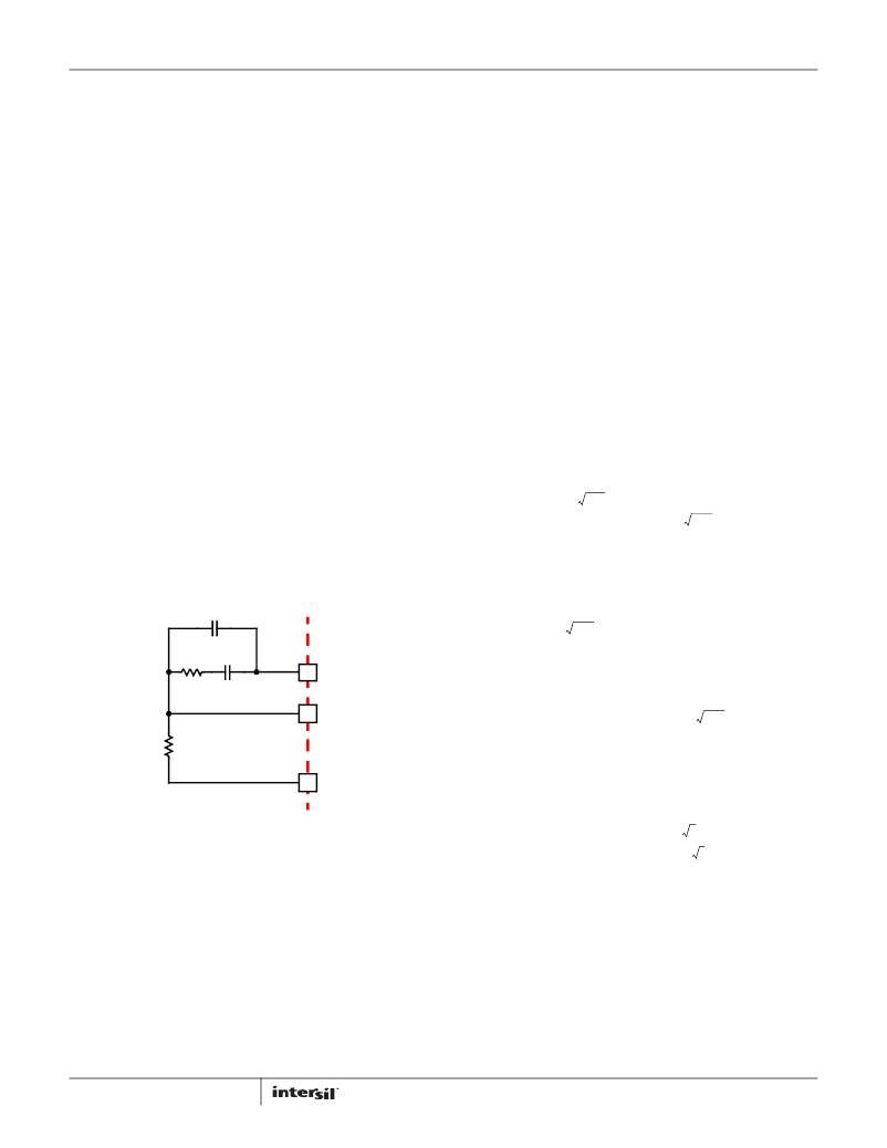
�The� optional� capacitor� C� 2� ,� is� sometimes� needed� to� bypass� noise�
�away� from� the� PWM� comparator� (see� Figure� 20).� Keep� a� position�
�available� for� C� 2� ,� and� be� prepared� to� install� a� high-frequency�
�capacitor� of� between� 22pF� and� 150pF� in� case� any� leading� edge�
�jitter� problem� is� noted.�
�1�
�2� ?� π� ?� L� ?� C�
�0.66� ?� V�
�R� C� =� R� FB� ?� ------------------------------------------------------�
�IN�
�0.66� ?� V� IN�
�C� C� =� --------------------------------------------------�
�-------------------------------� ≤� f� 0� <� -----------------------------------�
�2� ?� π� ?� L� ?� C�
�C� 2� (OPTIONAL)�
�Case� 2:�
�1� 1�
�2� ?� π� ?� C� ?� ESR�
�V� PP� ?� (� 2� ?� π� )� 2� ?� f� 02� ?� L� ?� C�
�C� C� =� ----------------------------------------------------------------------------------�
�PP� ?� R� FB� ?�
�(� 2� ?� π� )� 2� ?� f� 2� ?� V� L� ?� C�
�f� 0� >� -----------------------------------�
�R� FB�
�R� C�
�C� C�
�COMP�
�FB�
�VSEN�
�ISL6328�
�Case� 3:�
�0.66� ?� V�
�R� C� =� R� FB� ?� ---------------------------------------------------------------�
�IN�
�0.66� ?� V� IN�
�0�
�1�
�2� ?� π� ?� C� ?� ESR�
�(EQ.� 36)�
�R� C� =� R� FB� ?� -------------------------------------------�
�2� ?� π� ?� V� PP� ?� R� FB� ?� f� 0� ?� L�
�FIGURE� 20.� COMPENSATION� CONFIGURATION� FOR�
�LOAD-LINE� REGULATED� ISL6328� CIRCUIT�
�Since� the� system� poles� and� zero� are� affected� by� the� values� of� the�
�components� that� are� meant� to� compensate� them,� the� solution� to�
�the� system� equation� becomes� fairly� complicated.� Fortunately,�
�there� is� a� simple� approximation� that� comes� very� close� to� an�
�optimal� solution.� Treating� the� system� as� though� it� were� a� voltage-�
�mode� regulator,� by� compensating� the� L-C� poles� and� the� ESR� zero�
�of� the� voltage� mode� approximation,� yields� a� solution� that� is�
�always� stable� with� very� close� to� ideal� transient� performance.�
�Select� a� target� bandwidth� for� the� compensated� system,� f� 0� .� The�
�target� bandwidth� must� be� large� enough� to� assure� adequate�
�transient� performance,� but� smaller� than� 1/3� of� the� per-channel�
�switching� frequency.� The� values� of� the� compensation�
�26�
�2� ?� π� ?� f� 0� ?� V� pp� ?� L�
�0.66� ?� V� IN� ?� ESR�
�0.66� ?� V� IN� ?� ESR� ?� C�
�C� C� =� --------------------------------------------------------------�
�Compensation� Without� Loadline� Regulation�
�The� non� load-line� regulated� converter� is� accurately� modeled� as� a�
�voltage-mode� regulator� with� two� poles� at� the� L-C� resonant�
�frequency� and� a� zero� at� the� ESR� frequency.� A� type� III� controller,�
�as� shown� in� Figure� 21,� provides� the� necessary� compensation.�
�FN7621.1�
�June� 7,� 2011�
�相关PDF资料 |
PDF描述 |
|---|---|
| LB16WGW01 | SWITCH PUSHBUTTON SPDT 3A 125V |
| ISL6328CRZ-T | IC CTRLR PWM SYNC BUCK DL 48QFN |
| LB16WKW01 | SWITCH PUSHBUTTON SPDT 3A 125V |
| X9315WMIZ-2.7T1R5419 | IC DGTL POT 32POS 10K 8MSOP |
| YB15WCKG01-BB | SWITCH PUSH SPDT 0.4VA 28V |
相关代理商/技术参数 |
参数描述 |
|---|---|
| ISL6329CRZ | 功能描述:电压模式 PWM 控制器 6+1 PHS DL PWM CONTRLR FOR CORE RoHS:否 制造商:Texas Instruments 输出端数量:1 拓扑结构:Buck 输出电压:34 V 输出电流: 开关频率: 工作电源电压:4.5 V to 5.5 V 电源电流:600 uA 最大工作温度:+ 125 C 最小工作温度:- 40 C 封装 / 箱体:WSON-8 封装:Reel |
| ISL6329CRZ-T | 功能描述:电压模式 PWM 控制器 6+1 PHS DL PWM CONTRLR FOR CORE RoHS:否 制造商:Texas Instruments 输出端数量:1 拓扑结构:Buck 输出电压:34 V 输出电流: 开关频率: 工作电源电压:4.5 V to 5.5 V 电源电流:600 uA 最大工作温度:+ 125 C 最小工作温度:- 40 C 封装 / 箱体:WSON-8 封装:Reel |
| ISL6329EVAL1Z | 制造商:Intersil Corporation 功能描述:ISL6329 EVALUATION BOARD - 60 LEAD - QFN - ROHS COMPLIANT - Bulk |
| ISL6329IRZ | 功能描述:电压模式 PWM 控制器 6+1 PHS DL PWM CONTRLR FOR CORE RoHS:否 制造商:Texas Instruments 输出端数量:1 拓扑结构:Buck 输出电压:34 V 输出电流: 开关频率: 工作电源电压:4.5 V to 5.5 V 电源电流:600 uA 最大工作温度:+ 125 C 最小工作温度:- 40 C 封装 / 箱体:WSON-8 封装:Reel |
| ISL6329IRZ-T | 功能描述:电压模式 PWM 控制器 6+1 PHS DL PWM CONTRLR FOR CORE RoHS:否 制造商:Texas Instruments 输出端数量:1 拓扑结构:Buck 输出电压:34 V 输出电流: 开关频率: 工作电源电压:4.5 V to 5.5 V 电源电流:600 uA 最大工作温度:+ 125 C 最小工作温度:- 40 C 封装 / 箱体:WSON-8 封装:Reel |
发布紧急采购,3分钟左右您将得到回复。