参数资料
| 型号: | ISL6441IR-TK |
| 厂商: | Intersil |
| 文件页数: | 11/18页 |
| 文件大小: | 0K |
| 描述: | IC CTRLR PWM DUAL 1.4MHZ 28-QFN |
| 标准包装: | 1,000 |
| 应用: | 电源 |
| 电流 - 电源: | 2mA |
| 电源电压: | 5.6 V ~ 24 V |
| 工作温度: | -40°C ~ 85°C |
| 安装类型: | 表面贴装 |
| 封装/外壳: | 28-VFQFN 裸露焊盘 |
| 供应商设备封装: | 28-QFN 裸露焊盘(5x5) |
| 包装: | 带卷 (TR) |
�� �
�
�ISL6441�
�The� internal� LDO� can� source� over� 60mA� to� supply� the� IC,�
�power� the� low� side� gate� drivers,� charge� the� external� boot�
�capacitor� and� supply� small� external� loads.� When� driving�
�large� FETs� especially� at� 1.4MHz� frequency,� little� or� no�
�regulator� current� may� be� available� for� external� loads.�
�For� example,� a� single� large� FET� with� 15nC� total� gate� charge�
�requires� 15nC� x� 1.4MHz� =� 21mA.� Also,� at� higher� input�
�voltages� with� larger� FETs,� the� power� dissipation� across� the�
�internal� 5V� will� increase.� Excessive� dissipation� across� this�
�regulator� must� be� avoided� to� prevent� junction� temperature�
�rise.� Larger� FETs� can� be� used� with� 5V� ±10%� input�
�applications.� The� thermal� overload� protection� circuit� will� be�
�triggered� if� the� VCC_5V� output� is� short� circuited.� Connect�
�VCC_5V� to� V� IN� for� 5V� ±10%� input� applications.�
�Soft-Start� Operation�
�When� soft-start� is� initiated,� the� voltage� on� the� SS� pin� of� the�
�enabled� PWM� channels� starts� to� ramp� gradually,� due� to� the�
�5μA� current� sourced� into� the� external� capacitor.� The� output�
�voltage� follows� the� soft-start� voltage.�
�When� the� SS� pin� voltage� reaches� 0.8V,� the� output� voltage� of�
�the� enabled� PWM� channel� reaches� the� regulation� point,� and�
�the� soft-start� pin� voltage� continues� to� rise.� At� this� point� the�
�PGOOD� and� fault� circuitry� is� enabled.� This� completes� the�
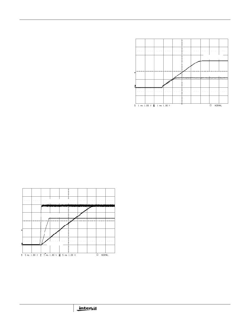
�C� SS1� /C� SS2� =� 1.2/3.3� =� 0.364.� Figure� 14� shows� that� soft-start�
�waveform� with� C� SS1� =� 0.01μF� and� C� SS2� =� 0.027μF.�
�V� OUT2� 1V/DIV�
�V� OUT1� 1V/DIV�
�FIGURE� 14.� PWM1� AND� PWM2� OUTPUT� TRACKING� DURING�
�START-UP�
�Output� Voltage� Programming�
�A� resistive� divider� from� the� output� to� ground� sets� the� output�
�voltage� of� either� PWM� channel.� The� center� point� of� the�
�divider� shall� be� connected� to� FBx� pin.� The� output� voltage�
�value� is� determined� by� Equation� 2.�
�V� OUTx� =� 0.8V� ?� ?�
�?� R� 1� +� R� 2� ?�
�soft-start� sequence.� Any� further� rise� of� SS� pin� voltage� does�
�not� affect� the� output� voltage.� By� varying� the� values� of� the�
�soft-start� capacitors,� it� is� possible� to� provide� sequencing� of� the�
�?� R� 2� ?�
�---------------------�
�(EQ.� 2)�
�main� outputs� at� start-up.� The� soft-start� time� can� be� obtained�
�from� Equation� 1:�
�where� R� 1� is� the� top� resistor� of� the� feedback� divider� network�
�and� R� 2� is� the� resistor� connected� from� FBx� to� ground.�
�T� SOFT� =� 0.8V� ?� -----------� ?�
�C� SS�
�?� 5� μ� A� ?�
�VCC_5V 1V/DIV�
�V� OUT1� 1V/DIV�
�SS1 1V/DIV�
�(EQ.� 1)�
�Out-of-Phase� Operation�
�The� two� PWM� controllers� in� the� ISL6441� operate� 180� °�
�out-of-phase� to� reduce� input� ripple� current.� This� reduces� the�
�input� capacitor� ripple� current� requirements,� reduces� power�
�supply-induced� noise,� and� improves� EMI.� This� effectively�
�helps� to� lower� component� cost,� save� board� space� and�
�reduce� EMI.�
�Dual� PWMs� typically� operate� in-phase� and� turn� on� both�
�upper� FETs� at� the� same� time.� The� input� capacitor� must� then�
�support� the� instantaneous� current� requirements� of� both�
�controllers� simultaneously,� resulting� in� increased� ripple�
�voltage� and� current.� The� higher� RMS� ripple� current� lowers�
�the� efficiency� due� to� the� power� loss� associated� with� the� ESR�
�of� the� input� capacitor.� This� typically� requires� more� low-ESR�
�capacitors� in� parallel� to� minimize� the� input� voltage� ripple� and�
�ESR-related� losses,� or� to� meet� the� required� ripple� current�
�rating.�
�FIGURE� 13.� SOFT-START� OPERATION�
�The� soft-start� capacitors� can� be� chosen� to� provide� start-up�
�tracking� for� the� two� PWM� outputs.� This� can� be� achieved� by�
�choosing� the� soft-start� capacitors� such� that� the� soft-start�
�capacitor� ration� equals� the� respective� PWM� output� voltage�
�ratio.� For� example,� if� I� use� PWM1� =� 1.2V� and� PWM2� =� 3.3V�
�then� the� soft-start� capacitor� ration� should� be,�
�11�
�With� dual� synchronized� out-of-phase� operation,� the�
�high-side� MOSFETs� of� the� ISL6441� turn� on� 180� °�
�out-of-phase.� The� instantaneous� input� current� peaks� of� both�
�regulators� no� longer� overlap,� resulting� in� reduced� RMS�
�ripple� current� and� input� voltage� ripple.� This� reduces� the�
�required� input� capacitor� ripple� current� rating,� allowing� fewer�
�or� less� expensive� capacitors,� and� reducing� the� shielding�
�FN9197.3�
�May� 26,� 2009�
�相关PDF资料 |
PDF描述 |
|---|---|
| ISL6443AIVZ | IC CTRLR SGL/STP DWN PWM 28TSSOP |
| ISL6443IR-TK | IC CTRLR PWM DUAL 300KHZ 28-QFN |
| ISL6444CA-T | IC CONTROLLER DDR 28-QSOP |
| ISL6445IAZ | IC REG CTRLR BUCK PWM CM 24-QSOP |
| ISL6455AIRZS2698 | IC REG TRPL SYNC DUAL LDO 24-QFN |
相关代理商/技术参数 |
参数描述 |
|---|---|
| ISL6441IRZ | 功能描述:IC CTRLR SGL/STEP DOWN PWM 28QFN RoHS:是 类别:集成电路 (IC) >> PMIC - 电源管理 - 专用 系列:- 产品培训模块:Lead (SnPb) Finish for COTS Obsolescence Mitigation Program 标准包装:50 系列:- 应用:热电冷却器 电流 - 电源:- 电源电压:3 V ~ 5.5 V 工作温度:-40°C ~ 85°C 安装类型:表面贴装 封装/外壳:28-SOIC(0.173",4.40mm 宽)裸露焊盘 供应商设备封装:28-TSSOP 裸露焊盘 包装:管件 产品目录页面:1410 (CN2011-ZH PDF) |
| ISL6441IRZS2695 | 制造商:Intersil Corporation 功能描述: |
| ISL6441IRZ-T | 功能描述:IC CTRLR PWM DUAL 1.4MHZ 28-QFN RoHS:是 类别:集成电路 (IC) >> PMIC - 电源管理 - 专用 系列:- 应用说明:Ultrasound Imaging Systems Application Note 产品培训模块:Lead (SnPb) Finish for COTS Obsolescence Mitigation Program 标准包装:37 系列:- 应用:医疗用超声波成像,声纳 电流 - 电源:- 电源电压:2.37 V ~ 6 V 工作温度:0°C ~ 70°C 安装类型:表面贴装 封装/外壳:56-WFQFN 裸露焊盘 供应商设备封装:56-TQFN-EP(8x8) 包装:管件 |
| ISL6441IRZ-TK | 功能描述:IC CTRLR PWM 1.4MHZ DUAL 28-QFN RoHS:是 类别:集成电路 (IC) >> PMIC - 电源管理 - 专用 系列:- 应用说明:Ultrasound Imaging Systems Application Note 产品培训模块:Lead (SnPb) Finish for COTS Obsolescence Mitigation Program 标准包装:37 系列:- 应用:医疗用超声波成像,声纳 电流 - 电源:- 电源电压:2.37 V ~ 6 V 工作温度:0°C ~ 70°C 安装类型:表面贴装 封装/外壳:56-WFQFN 裸露焊盘 供应商设备封装:56-TQFN-EP(8x8) 包装:管件 |
| ISL6442EVAL1Z | 功能描述:EVAL BOARD FOR ISL6442 RoHS:是 类别:编程器,开发系统 >> 评估板 - DC/DC 与 AC/DC(离线)SMPS 系列:- 产品培训模块:Obsolescence Mitigation Program 标准包装:1 系列:True Shutdown™ 主要目的:DC/DC,步升 输出及类型:1,非隔离 功率 - 输出:- 输出电压:- 电流 - 输出:1A 输入电压:2.5 V ~ 5.5 V 稳压器拓扑结构:升压 频率 - 开关:3MHz 板类型:完全填充 已供物品:板 已用 IC / 零件:MAX8969 |
发布紧急采购,3分钟左右您将得到回复。