参数资料
| 型号: | ISL6441IR-TK |
| 厂商: | Intersil |
| 文件页数: | 17/18页 |
| 文件大小: | 0K |
| 描述: | IC CTRLR PWM DUAL 1.4MHZ 28-QFN |
| 标准包装: | 1,000 |
| 应用: | 电源 |
| 电流 - 电源: | 2mA |
| 电源电压: | 5.6 V ~ 24 V |
| 工作温度: | -40°C ~ 85°C |
| 安装类型: | 表面贴装 |
| 封装/外壳: | 28-VFQFN 裸露焊盘 |
| 供应商设备封装: | 28-QFN 裸露焊盘(5x5) |
| 包装: | 带卷 (TR) |
�� �
�
�ISL6441�
�Output� Inductor� Selection�
�The� PWM� converters� require� output� inductors.� The� output�
�inductor� is� selected� to� meet� the� output� voltage� ripple�
�5.0�
�4.5�
�requirements.� The� inductor� value� determines� the� converter� ’s�
�ripple� current� and� the� ripple� voltage� is� a� function� of� the� ripple�
�current� and� output� capacitor(s)� ESR.� The� ripple� voltage�
�expression� is� given� in� the� “Output� Capacitor� Selection”� on�
�page� 16� or� “Input� Capacitor� Selection”� on� page� 17� and� the�
�ripple� current� is� approximated� by� Equation� 15:�
�4.0�
�3.5�
�3.0�
�2.5�
�2.0�
�IN PHASE�
�OUT-OF-PHASE�
�Δ� I� L� =� ----------------------------------------------------------�
�(� V� IN� –� V� OUT� )� (� V� OUT� )�
�(� f� S� )� (� L� )� (� V� IN� )�
�(EQ.� 15)�
�1.5�
�1.0�
�0.5�
�3.3V�
�5V�
�For� the� ISL6441,� Inductor� values� between� 1μH� to� 3.3μH� is�
�0�
�0�
�1�
�2� 3�
�4�
�5�
�recommended� when� using� the� “Typical� Application�
��rigorous� stability� analysis� should� be� done.�
�Input� Capacitor� Selection�
�The� important� parameters� for� the� bulk� input� capacitor(s)� are�
�the� voltage� rating� and� the� RMS� current� rating.� For� reliable�
�operation,� select� bulk� input� capacitors� with� voltage� and�
�current� ratings� above� the� maximum� input� voltage� and� largest�
�RMS� current� required� by� the� circuit.� The� capacitor� voltage�
�rating� should� be� at� least� 1.25x� greater� than� the� maximum�
�input� voltage� and� 1.5x� is� a� conservative� guideline.� The� AC�
�RMS� Input� current� varies� with� the� load.� The� total� RMS�
�current� supplied� by� the� input� capacitance� is� as� shown� in�
�Equations� 16� and� 17:�
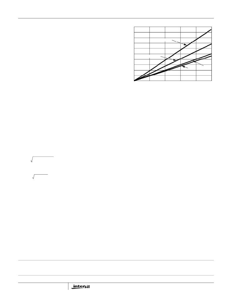
�3.3V� AND� 5V� LOAD� CURRENT�
�FIGURE� 22.� INPUT� RMS� CURRENT� vs� LOAD�
�Use� a� mix� of� input� bypass� capacitors� to� control� the� voltage�
�ripple� across� the� MOSFETs.� Use� ceramic� capacitors� for� the�
�high� frequency� decoupling� and� bulk� capacitors� to� supply� the�
�RMS� current.� Small� ceramic� capacitors� can� be� placed� very�
�close� to� the� upper� MOSFET� to� suppress� the� voltage� induced�
�in� the� parasitic� circuit� impedances.�
�For� board� designs� that� allow� through-hole� components,� the�
�Sanyo� OS-CON?� series� offer� low� ESR� and� good�
�temperature� performance.� For� surface� mount� designs,� solid�
�tantalum� capacitors� can� be� used,� but� caution� must� be�
�exercised� with� regard� to� the� capacitor� surge� current� rating.�
�These� capacitors� must� be� capable� of� handling� the�
�I� RMS� =�
�2� 2�
�I� RMS1� +� I� RMS2�
�(EQ.� 16)�
�surge-current� at� power-up.� The� TPS� series� available� from�
�AVX� is� surge� current� tested.�
�where,�
�I� RMSx� =�
�DC� –� DC�
�2�
�(EQ.� 17)�
�DC� is� duty� cycle� of� the� respective� PWM.�
�Depending� on� the� specifics� of� the� input� power� and� its�
�impedance,� most� (or� all)� of� this� current� is� supplied� by� the�
�input� capacitor(s).� Figure� 22� shows� the� advantage� of� having�
�the� PWM� converters� operating� out-of-phase.� If� the�
�converters� were� operating� in� phase,� the� combined� RMS�
�current� would� be� the� algebraic� sum,� which� is� a� much� larger�
�value� as� shown.� The� combined� out-of-phase� current� is� the�
�square� root� of� the� sum� of� the� square� of� the� individual�
�reflected� currents� and� is� significantly� less� than� the� combined�
�in-phase� current.�
�All� Intersil� U.S.� products� are� manufactured,� assembled� and� tested� utilizing� ISO9000� quality� systems.�
�Intersil� Corporation’s� quality� certifications� can� be� viewed� at� www.intersil.com/design/quality�
�Intersil� products� are� sold� by� description� only.� Intersil� Corporation� reserves� the� right� to� make� changes� in� circuit� design,� software� and/or� specifications� at� any� time� without�
�notice.� Accordingly,� the� reader� is� cautioned� to� verify� that� data� sheets� are� current� before� placing� orders.� Information� furnished� by� Intersil� is� believed� to� be� accurate� and�
�reliable.� However,� no� responsibility� is� assumed� by� Intersil� or� its� subsidiaries� for� its� use;� nor� for� any� infringements� of� patents� or� other� rights� of� third� parties� which� may� result�
�from� its� use.� No� license� is� granted� by� implication� or� otherwise� under� any� patent� or� patent� rights� of� Intersil� or� its� subsidiaries.�
�For� information� regarding� Intersil� Corporation� and� its� products,� see� www.intersil.com�
�17�
�FN9197.3�
�May� 26,� 2009�
�相关PDF资料 |
PDF描述 |
|---|---|
| ISL6443AIVZ | IC CTRLR SGL/STP DWN PWM 28TSSOP |
| ISL6443IR-TK | IC CTRLR PWM DUAL 300KHZ 28-QFN |
| ISL6444CA-T | IC CONTROLLER DDR 28-QSOP |
| ISL6445IAZ | IC REG CTRLR BUCK PWM CM 24-QSOP |
| ISL6455AIRZS2698 | IC REG TRPL SYNC DUAL LDO 24-QFN |
相关代理商/技术参数 |
参数描述 |
|---|---|
| ISL6441IRZ | 功能描述:IC CTRLR SGL/STEP DOWN PWM 28QFN RoHS:是 类别:集成电路 (IC) >> PMIC - 电源管理 - 专用 系列:- 产品培训模块:Lead (SnPb) Finish for COTS Obsolescence Mitigation Program 标准包装:50 系列:- 应用:热电冷却器 电流 - 电源:- 电源电压:3 V ~ 5.5 V 工作温度:-40°C ~ 85°C 安装类型:表面贴装 封装/外壳:28-SOIC(0.173",4.40mm 宽)裸露焊盘 供应商设备封装:28-TSSOP 裸露焊盘 包装:管件 产品目录页面:1410 (CN2011-ZH PDF) |
| ISL6441IRZS2695 | 制造商:Intersil Corporation 功能描述: |
| ISL6441IRZ-T | 功能描述:IC CTRLR PWM DUAL 1.4MHZ 28-QFN RoHS:是 类别:集成电路 (IC) >> PMIC - 电源管理 - 专用 系列:- 应用说明:Ultrasound Imaging Systems Application Note 产品培训模块:Lead (SnPb) Finish for COTS Obsolescence Mitigation Program 标准包装:37 系列:- 应用:医疗用超声波成像,声纳 电流 - 电源:- 电源电压:2.37 V ~ 6 V 工作温度:0°C ~ 70°C 安装类型:表面贴装 封装/外壳:56-WFQFN 裸露焊盘 供应商设备封装:56-TQFN-EP(8x8) 包装:管件 |
| ISL6441IRZ-TK | 功能描述:IC CTRLR PWM 1.4MHZ DUAL 28-QFN RoHS:是 类别:集成电路 (IC) >> PMIC - 电源管理 - 专用 系列:- 应用说明:Ultrasound Imaging Systems Application Note 产品培训模块:Lead (SnPb) Finish for COTS Obsolescence Mitigation Program 标准包装:37 系列:- 应用:医疗用超声波成像,声纳 电流 - 电源:- 电源电压:2.37 V ~ 6 V 工作温度:0°C ~ 70°C 安装类型:表面贴装 封装/外壳:56-WFQFN 裸露焊盘 供应商设备封装:56-TQFN-EP(8x8) 包装:管件 |
| ISL6442EVAL1Z | 功能描述:EVAL BOARD FOR ISL6442 RoHS:是 类别:编程器,开发系统 >> 评估板 - DC/DC 与 AC/DC(离线)SMPS 系列:- 产品培训模块:Obsolescence Mitigation Program 标准包装:1 系列:True Shutdown™ 主要目的:DC/DC,步升 输出及类型:1,非隔离 功率 - 输出:- 输出电压:- 电流 - 输出:1A 输入电压:2.5 V ~ 5.5 V 稳压器拓扑结构:升压 频率 - 开关:3MHz 板类型:完全填充 已供物品:板 已用 IC / 零件:MAX8969 |
发布紧急采购,3分钟左右您将得到回复。